SLC 5/05 With 1747-SN and PanelView

atwell3993

Member
Join Date
May 2016
Location
Indianapolis
Posts
22
Hi,

I am inheriting a system that uses a SLC 5/05 processor that has a PanelView 1000 attached to it through a 1747-SN module. On that same RIO module, there are three Panther scales attached to it.

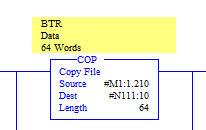
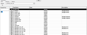
I have the .PVA file from the PanelView, and the .RSS file. In the Panel view application, the tags are named things like "Line L Scale Setpoint", then those are (apparently) brought in via the M file and Copied with length 64 to the N111 data file.

In the PVA application, which I have opened in Factory Talk View Studio - Machine Edition, I can not find how those tags are mapped to the M data file, AKA, in what order are they set up?

We are looking at removing the panel view, and I want to make sure I am not going to ruin this RIO chain by removing the panel view.

Thanks!
TagsInPanelView.png CopyInstruction.png
 
In the PVA application, which I have opened in Factory Talk View Studio - Machine Edition, I can not find how those tags are mapped to the M data file, AKA, in what order are they set up?
The data for the Panelview tags will be in the N111 data file. In the properties of each tag there shall be a "data source" property.

Disclaimer: It has been 20 years since I dabbled with Panelview.
 
Hi Jesper,

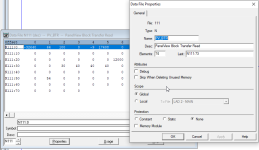
Thank you for the quick reply! When I look in the N111 Data File Properties this is all that I get:

Is there any way in FTView ME to view the block builder like you could in older programs like PanelBuilder 1400e or PB32 (from what I've heard - I have no experience with either)?

N111_Properties.png
 
I dont know the current FTView ME, but I am guessing that in the window from your 1st screenshot, you can doubleclick on each tag line and get up a new window with the details of the tags properties.
Or maybe right-click on a tag, a menu appears, and you have to select "properties" or something like that.
 
Actually, one can glimpse a line called "data source" in the 1st screenshot.
What happens when you change from "Device" to "Memory" ?
What happens when you hit the [...] button ?
 
Ummmm . . . Would the N111 data file be in the SLC or the Panelview ?
(Or both - read into the Panelview from the SLC?)
 
Jesper, unfortunately no matter what I have selected in the N111 data file, the properties window displays the properties for the whole data file, not the bit, word, or row I have selected. If I change the data source to Memory it simply brings up a text box where I can indicate a value and choose to make it retentive or not.

Mad_poet, the N111 data file is in the SLC, is it being copied all the values from the M1:1.210 data file with length 64. I am trying to figure out how to view / modify that M1 data file.

My current understanding is that this can only be done via PanelBuilder32 for this model, but I do not have access to that software.
 
There may not be any symbols or descriptions in the N111 file for each the integer addresses.
It is sloppy by the original programmer, but it does look like that.
If this had been a Controllogix program, each PLC tag would at least have had a symbolic name.

If you can get to open the original panelview program, and find the addresses each tag is conected to, you could add some symbols or descriptions by reverse engineering.

What is "this model", Panelview 1000, or Panelview Plus 1000 ?
Exactly what is the type no ?
 
I just came to realise that I assumed the panelview is connected via Ethernet, since the SLC5/05 have ethernet onboard.
Is the panelview actually connected via RIO ? In that case, the tag setup is totally different, and you wont see the SLC addresses in the Panelview.

edit: I have done Panelviews on RIO in the past. It is really really funky ! One may ask, why go via RIO when you have ethernet ?

edit again: If the Panelview is really on RIO, I have to respectfully bow out ! I suggest study the manuals !!
 
Last edited:
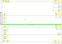
So, this data is moved back and forth between N111 and N110 via hard coded BTW/BTR like logic (instead of the BTW and BTR commands, no idea why, not a ton of experience with them).

In that N110 file I do have descriptions that I can likely use to be able to directly address the bits/words I want on my new Wonderware HMI.

My concerns are two fold:
1. The N111 word is used outside of the BTW/BTR on three occasions, and I can not comprehend why.
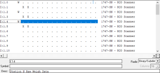
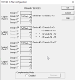
2. In the previous setup, there were three scales, now there will only be one. So I do not know what is going to happen with that M data file, and the 1747-SN G config file when I remove the other two scales. The G config file is puzzling to me as well as the scale data maps to I:1.0-I:1.5 despite the fact that the G config is not set up for that (picture attached). This integrators whole programming strategy just baffles me.

I feel ignorant having so many questions, I am just a junior engineer trying to work with stuff that's almost as old as I am haha.

BTW_BTR.png inputfile.png gconfig.png
 
Jesper, it is definitely on RIO unfortunately...at least that's what the schematics I have seen say haha...you know how accurate those usually are. Unfortunately I have not seen the actual equipment yet.

Thank you for all of your help!
 
Can't really help but can you post the PB32 file? Maybe someone with access to the software could assist.
Or contact you local RA distributor for help with getting the PB software.
 
For Clarification is the Panelview running PB32 Software you mentioned in the Original
post opening the PBA in Factory talk View ME. I know you can convert PB32 to FTVME
with the conversion tools in FTVME but thats not the same as looking at a PB32 FILE.
What is the scope of the project, Replace the 2711 HMI and go with a different brand.
 

Similar Topics

Looking for some help with downloading to a Panelview 1400e via a SLC 5/04 and 1747-SN,B RIO scanner. The 1747-SN,B is configured for racks 0-3...
Replies
2
Views
10,464
Hello, I've got a project where I need to get information from two ABB ACS880 VFDs onto the plant operator's screen (or alternatively, onto...
Replies
23
Views
2,574
I have the following Items connected for DH-485 per the drawing. SLC 5/03 HMI: Automation Direct EA9-T10CL+13Y19B054 1747-AIC #1: connected...
Replies
10
Views
3,041
Hello, First I looked at Manuel and Plctalk but I did not find or maybe not understand. How I can connect ''HTL / Push pull-24 volt encoder'' to...
Replies
4
Views
2,519
Hello I will make it short and sweet. I need the cable that goes from the slc 501 to the 1747-UIC RJ-45 connection. From what I can find it...
Replies
3
Views
1,240
Back
Top Bottom