Ladder method program

BHEKI

Member
Join Date
Nov 2014
Location
Eastern Cape
Posts
10
Im new to PLC programming and im trying to write a program which will open a boom(that is running a motor forward), stop and close the boom(reverse the dc motor) maybe after 10second.

Im working on a small project which monitors the cars that are coming inside the car park, as they come to a car park they must be counted and also be decremented as they get out of the parking lot. if the number of cars entering the car park equal the number of parking lot the boom on the entry side must not be activated at all until one or more cars leaves the car park.

I need help on how I can first be able to program one boom gate as to open, stop and close after. The type of PLC Im using is SIEMENS S7-200
 
Hi there,
This subject has come up many times on this and other forums.
I just did a search on this forum and seen lots of threads that have already covered this.
Use the search function and search for:
Garage Door
Parking Garage
Car Park

All three of these will turn up lots of information and should show you exactly what you are looking for.

After you have searched and read through these existing treads, if you have more specific quesions then post them and forum members will be happy to assist you.

Good Luck with your project,
BCS
 
I'm working on a small project which monitors the cars that are coming inside the car park, as they come to a car park they must be counted...

In your other post on this project, did you figure out what voltage you needed on the S7-200 terminal "1L" to make your relays operate?

http://www.plctalk.net/qanda/showthread.php?t=91453

How many sensors do you have at the entry gate, and at the exit gate? If only 1 at each point, then you have a somewhat dangerous situation, because a car may stop under the gate, and the gate will lower onto the car. The driver may change his mind and drive away, so that your counter is 1 more than the number of cars in your car park, causing a loss of revenue.

If you place a sensor on the Inside and another on the Outside of the gate, then you can detect a car wanting to enter (raise gate by activating the Entrance Gate Up Motor Output), and also if it actually enters (activate the Entrance Gate Down Motor Output). Then you can increment the "Cars in Park" counter by 1 and know that it is correct.

The same applies to the Exit Gate. Place a vehicle sensor on the inside and the outside of the gate. When the Exit Inside sensor is triggered, activate the Exit Gate Up Motor Output. When the Exit Outside sensor is triggered, activate the Exit Gate Down Motor Output, and also Decrement (Count Down) by 1 the "Cars in Park" Counter.

Without the 2 extra sensors, you are restricted to using a timer that may or may not allow enough time for a car to move out of the way of the gate, and it will not detect if a car quits while under the gate. Also your count may be incorrect due to cars not enterning AND cars not leaving.
 
Last edited:
In your other post on this project, did you figure out what voltage you needed on the S7-200 terminal "1L" to make your relays operate?

http://www.plctalk.net/qanda/showthread.php?t=91453

How many sensors do you have at the entry gate, and at the exit gate? If only 1 at each point, then you have a somewhat dangerous situation, because a car may stop under the gate, and the gate will lower onto the car. The driver may change his mind and drive away, so that your counter is 1 more than the number of cars in your car park, causing a loss of revenue.

If you place a sensor on the Inside and another on the Outside of the gate, then you can detect a car wanting to enter (raise gate by activating the Entrance Gate Up Motor Output), and also if it actually enters (activate the Entrance Gate Down Motor Output). Then you can increment the "Cars in Park" counter by 1 and know that it is correct.

The same applies to the Exit Gate. Place a vehicle sensor on the inside and the outside of the gate. When the Exit Inside sensor is triggered, activate the Exit Gate Up Motor Output. When the Exit Outside sensor is triggered, activate the Exit Gate Down Motor Output, and also Decrement (Count Down) by 1 the "Cars in Park" Counter.

Without the 2 extra sensors, you are restricted to using a timer that may or may not allow enough time for a car to move out of the way of the gate, and it will not detect if a car quits while under the gate. Also your count may be incorrect due to cars not enterning AND cars not leaving.

I have two sensors both on the entry side and exit side as to avoid what you just explained, I could only run one dc motor that is forward>>stop, reverse>>stop mode and increment the count only for entry side because my inputs are limited to only 8inputs(I0.0-I0.7). I used 5 inputs and I couldn't finish the exit side that is opening>>stop, closing>>stop and decrement the count.

I also have a problem with the DC MOTOR speed, will you please advice me of the motor that can run very slowly while opening, I want to use a geared dc motor but I'm not sure which one to use in terms of torque and rpm specification. I only used a 12VDC motor running at its full speed for testing my program.
 
Hi there,
This subject has come up many times on this and other forums.
I just did a search on this forum and seen lots of threads that have already covered this.
Use the search function and search for:
Garage Door
Parking Garage
Car Park

Thanks for the information, I did look at those and they were of help. THANK YOU
 
I also have a problem with the DC MOTOR speed, will you please advice me of the motor that can run very slowly while opening,
You need a model or hobby-type geared motor, similar to this one from another student project:
DC Geared Motor, "RS" Product SPG30-300K, 12 RPM, 410 miliamps, 1.1 watts, 1176 mN/m torque, 12 volts DC Input.

I used 5 inputs and I couldn't finish the exit side that is opening>>stop, closing>>stop and decrement the count.
Because you only have 8 Inputs, I suggest you do this:
Forget the Stop inputs for now. Use a timer to stop the motor when the gate is open or closed.

Inputs (You can get by with only the 5 listed below):
I0.0 System START/STOP selector switch
I0.1 Outside Entry Vehicle Sensor
I0.2 Inside Entry Vehicle Sensor
I0.3 Outside Exit Vehicle Sensor
I0.4 Inside Exit Vehicle Sensor

Outputs
Q0.0 Entrance Gate Motor UP
Q0.1 Entrance Gate Motor DOWN
Q0.2 Exit Gate Motor UP
Q0.3 Exit Gate Motor DOWN

Internal "M" Relays
M0.0 One-Shot
M0.1 Alternator
M0.2 System RUN
M0.3 Entry Vehicle Present
M0.4 Exit Vehicle Present
I could only run one dc motor that is forward>>stop, reverse>>stop mode and increment the count only for entry side
Do not use Inputs for Forward, Stop, Reverse, or Incrementing the Count. You do not need those. Use the ones that I listed above.

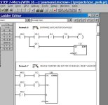
To Increase and Decrase the vehicle count, you do not need any additional Inputs. Do it like the attached picture.

Car Park Project Counter- Bheki.jpg
 
Last edited:
Here is a geared DC Motor at the RS-Online in South Africa site, RS Stock Number 752-1951, Como Drill Part Number 919D8101LN, Price R 397.32

http://za.rs-online.com/web/p/dc-motors/7521951/

This motor full speed is 5216 RPM, but it has a 810:1 gear reducer (see data sheet), so the gear reducer output at 12 volts is only 7 RPM. That is about what you need to turn a gate 90 degrees (1/4 revolution) in about 2 seconds.

7/60 = 0.1166 revolutions in 1 second.
90 degrees = 90/360 = 0.25 of 1 revolution

0.25/0.1166 = 2.14 seconds to open or close a gate at 7 RPM speed.
 
You need a model or hobby-type geared motor, similar to this one from another student project:
DC Geared Motor, "RS" Product SPG30-300K, 12 RPM, 410 miliamps, 1.1 watts, 1176 mN/m torque, 12 volts DC Input.


Because you only have 8 Inputs, I suggest you do this:
Forget the Stop inputs for now. Use a timer to stop the motor when the gate is open or closed.

Inputs (You can get by with only the 5 listed below):
I0.0 System START/STOP selector switch
I0.1 Outside Entry Vehicle Sensor
I0.2 Inside Entry Vehicle Sensor
I0.3 Outside Exit Vehicle Sensor
I0.4 Inside Exit Vehicle Sensor

Outputs
Q0.0 Entrance Gate Motor UP
Q0.1 Entrance Gate Motor DOWN
Q0.2 Exit Gate Motor UP
Q0.3 Exit Gate Motor DOWN

Internal "M" Relays
M0.0 One-Shot
M0.1 Alternator
M0.2 System RUN
M0.3 Entry Vehicle Present
M0.4 Exit Vehicle Present

Do not use Inputs for Forward, Stop, Reverse, or Incrementing the Count. You do not need those. Use the ones that I listed above.

To Increase and Decrase the vehicle count, you do not need any additional Inputs. Do it like the attached picture.

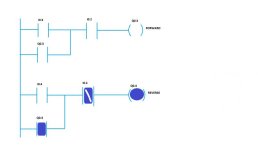
thanks for the information. I have tried using same inputs for stopping the motor from forward and reverse mode since the motor wont be In the forward and reverse mode at the same time.

But I have the problem reversing the second motor although on the display it looks ON.

What could be the problem?

PROGRAMM.jpg
 
Bheki,
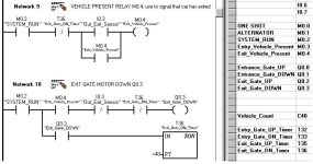
You need to develop 2 step relays M0.3 "Entry Vehicle Present" and M0.4 "Exit Vehicle Present". Think about how you really know that either gate is ready to be closed. First a vehicle must drive over the Entry Inside Sensor while the gate is UP. Then the vehicle must drive off of the Entry Inside Sensor (or the Exit Outside sensor). Only then do can you safely lower the gate. How can you build a bit that retains the data that a "vehlicle was present at the gate"? See the attached file for how to do that.

I also built a one-shot relay so that I could use a Start/Stop momentary-contact pushbutton (instead of a maintained-contact switch). If you do not need that, then you can delete the first 2 networks and bits M0.0 and M0.1.
 
Last edited:
I made a small error on the last rung 10. The I0.3 "Inside_Exit_Sensor" should have been the I0.4 "Outside_Exit_Sensor". Here is the correction.

Car Park- Bheki- Correction.JPG
 
Last edited:

Similar Topics

This question is addressed to those who have ample experience with both LL and ST. I know only ladder logic. I find that many a time it takes...
Replies
32
Views
26,938
Can somebody please explain to me the main differences between Shift Register and step Ladder programming also which is the best method to use and...
Replies
8
Views
8,099
Hi all. Is this the simplest way to debounce inputs in Ladder (there are 2 points being debounced here)? The TOF drives the tag. I'm expecting...
Replies
15
Views
480
I have a machine which is undergoing upgradation. As part of the process two SEW drives are being replaced., existing Gen B with new Gen C. The...
Replies
3
Views
193
Does anyone have RSLogix 5000 ladder diagram program of tank leveling (factory IO). Fill valve, discharge valve, set point, level, etc? I looked...
Replies
2
Views
155
Back
Top Bottom