MicroLogix 1000 Analog I/O

omars

Member
Join Date
Nov 2005
Location
toledo, oh
Posts
22
To Whom It May Concern:

I am working with a MicroLogix 1000 analog I/O module and it is the first time I have had to program analog I/O with it. I have the discrete I/O working fine but need advice on how I would write a program to test each analog I/O channel. It has two voltage inputs from 0-10 VDC and two current inputs from 4-20 mA. If it wouldn't be asking for too much, I would appreciate if someone could send me a sample program to test my I/O. Thank you in advance. - Omar
 
I am assuming from your inquiry that you have analog signals hooked up to the PLC and you want to observe the data to see if the signal is being read properly.

If you click on the O0 and I1 files on the left of the screen you can read the analog data directly. You may want to change the radix to "decimal"
 
The IO for analog is pre-assigned address. Look at your manual if you are unsure. You don't even need a program to see if the signal from outside is making it to your PLC. Simply take a 4-20ma simulator or a 9 VDC battery with pot and watch the address value change (in decimal) as you raise or lower input.


An easy thing to do with the analog input for experimenting is a compare function. You could turn an output off / on based on whether the input value is =, > or < a preset value. You could then move to scaling the input as a next step up. All you need to know is PLC min value at input min and the max of each (these are listed in the manual for the PLC) then what your min / max scale value is (500-5000 PSI, etc.) You can then try to turn a light on when you reach a value of 3500 PSI. It's simple and a real world application. Try it and post your attempt for further help.

 
ok, I gave it a try and it worked - sort of. I was able to use a greater than function to turn on an output coil. I was reading in the manual for the MicroLogix 1000 and it claims that you can put a decimal equivalent to whatever voltage or current you want to use in your output image table. I did this with 8 mA for example and I was indeed getting 8 mA flowing through the output. However, the output was on regardless of whether I had my source A input below or above my source B constant. I would like to be able to get the output current to change with my input value. I thought that was the purpose of using the PLC in the first place, instead of just programming in different values for the output current. What am I doing wrong?
 
You should first scale your raw counts into engineering units, (see this POST for scaling info or pehaps this ONE ).

That way if your input is 0-100 psi, you can use the values that have real meaning in you logic, such as if pressure is less than 50, turn on pump etc...

Another thought, if your having problems, just post your code, I'm sure someone will chime in with a helpful hint.


Ken
 
One things for sure, you are doing something wrong because you can do exactly what you are requesting. You will get alot of help if you post a picture of the lines of logic in your program you are talking about. If you are unsure how to do this, do a search on this forum about posting a JPEG with your comments for help.
 
Lets simplify this a little. Lets say you have a 0-10v input and need a 0-10v output, you dont have to do anything but MOV the input to the output. You scale the values to represent the 0-10v for display on an HMI or similar.
scalingtoO.jpg

To test the output use a digital meter (set for ma) in series with a resistor (or something) to check the current values...an analog output not connected to a device may not give proper results.
 
Last edited:
The point I was basically showing is scaling is not always necessary for the output....it depends. This example could get him/her started on understanding or seeing the output work.

It was basically an example and I didnt pay attention to the processor, I just opened an analog example and took a screen shot. The important part I wanted to show was moving input to output and what should be done to check it without any analog devices available.

I guess I should create an analog example using an ML1000.
 
Last edited:
Thank you for your help.

Thanks for the posts, guys. Tom was right though. All you need to do to check if the analog I/O is working is click on the I1 and O1 files to the left of the screen. I was able to run my inputs up and down and see the numbers change. I could also program decimal numbers into the analog output file and see the current/voltage change for each respective analog output. Thank you very much, indeed.
 
help code sample

hi pleace send code sample for my ml 1000 analog, I am novice and need to control temperature and ouput for mr5g motor controllers
thanks
joel
chile
 
I am relearning old programming skills and have been practising with a micrologix 1000 analog. I MOV a mid range and max range signal in my ladder logic to the analog output and the voltage out responds correctly... However when I check for milli amps with a meter or my milli amp panel indicator. (I have confirmed both work with my M.A. generator), i get nothing/ zero; and I am using, per the Micrologix 1000 manual analog schematic, the correct terminals OA/0 V+ and OA/0 - for voltage and OA/0 I+ and OA/0- for milli amps. I bought the PLC used and suspect it is faulty or I am missing something simple. I see Analog input devices need independent DC power supplied but I should be able to read milli amps across the analog out when wired for I. Am I missing something?
 
I should be able to read milli amps across the analog out when wired for I.

Across? You need to be in series with the current output.

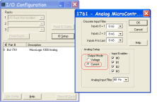
Also have you configured the output for current mode? see picture below.

output_Mode.png
 
THANKS MICKEY! It's been years since I have had hands on so yes I did not remember the proper configuration procedure and must have missed it when digging through the Manual.

You guys and this site are the best. I cannot say thanks enough!!

Jeff
 

Similar Topics

I need some help with scaling an analog input in an MicroLogix 1000 PLC with Analig IO. Its model # 1761-L20AWA-5A. I have more of these...
Replies
2
Views
6,068
Hi friends, I need communication cable PIN CONFIGURATIONS of AB micrologix 1000 analog PLC with PC. I'm willing to create new cable in my hand...
Replies
2
Views
2,314
Hello all. I have a problem trying to read 4-20mA into a Micrologix 1000 Analog PLC. Not sure if my issue is with wiring, or an option within the...
Replies
7
Views
3,488
Here's a tricky problem: I've just finished a program on a micrologix 1000 using a windows 2000 machine, and logix 500 at the house. When I got to...
Replies
6
Views
4,411
Hello friends I am very grateful for the help my post. now I need to regulate output analog 0-10v, with a sliders Rsview32 thank you joel...
Replies
0
Views
1,451
Back
Top Bottom