PID Tuning

gimli

Member
Join Date
Nov 2014
Location
nowhere
Posts
34
Hello All,


New at this and trying to tune a PID in Logix Designer.


Basically we have some electric heaters heating up some platens and no matter what pid settings i try its always overshooting by 80 degrees roughly. I think its because the pid starts throttling back the output right when it hits the PV setpoint..which is too late since it takes time for the heat from the heaters to get to the thermocouple. Not sure what setting would be good to help the PID anticipate that lag. Any suggestions would be great
thanks
🤾
 
The lag time between heater energy and what the sensor is seeing is your challenge.
Try reducing P and increasing I. Set D to zero. Sounds like you will be playing around for a good while since you have to wait for the platens to cool down before re-testing.

You can also buy a cheap temp controller to sub in temporarily since most of them they have PID auto-tune and after a few runs will have established parameters for P, I and D which will be in the ball park. I recently purchased a cheap one made in China and was pleased wit how it did the PID autotune. This was for electrically heating a small block of aluminum.
 
If you can provide the following information, there are people on this forum that can suggest PID settings that will likely get you in the ballpark of desired performance:

1. A trend chart showing open-loop step response of the process (e.g., screen shot of a Logix 5K trend). This chart should have the PID process variable (PV) and control variable (CV), and have time scale long enough that the PV has fully settled after the change in CV. You will make a step change in CV, via Set Output with the loop in Software Manual, and this step is ideally an amount typical for your process. Start with half the CV that your loop goes to when it overshoots by 80 degrees.
2. A screen shot of the PID "Configuration" tab (assuming PID, not PIDE instruction).
3. A screen shot of the PID "Scaling" tab (assuming PID, not PIDE instruction).
4. Optional, but possibly helpful, a screen shot of the rung containing the PID instruction.

While it is not always possible to provide this type of information for process and/or IP reasons, it will offer a quicker path to better PID performance.
 
Hi All,


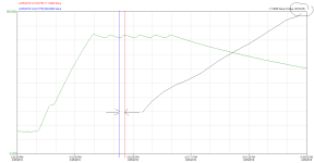
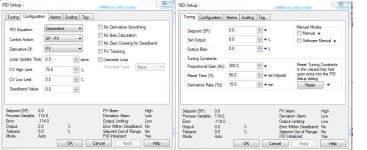
So its been a while, trying to get some good pid values but am still having difficulty..thanks for the response. This is what I have if anyone can suggest some settings. I attached a trend and PID settings. Set Point is 700 f
thanks much

trend.png pid2.JPG
 
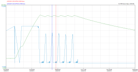
It looks like that trend is the closed-loop response to a product heat-up. If so, my initial reaction is that PID tuning is not the root cause of the (undamped) oscillation. Its appearance suggests a problem with the final control element, and if your heat supply was a fluid through a valve, a good place to look is valve "stiction." But since the initial post indicates resistance heating, that is probably not the case unless there is some controller output/resolution problem from the PLC to the heater controls. It would help to see the controller output (CV) as well as PV on this kind of trend.
 
I wrote a program that estimates the SOPDT model using Python about 6 months ago.
I posted it on this forum. It used data provided by Ron Beaufort many years ago for his 'HotRod' temperature control trainers.
It requires a tab separated text file with three columns of time, control, and PV.
 
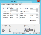
I'm going to take back my comment about PID tuning not helping; there is definitely some room for improvement. In order to suggest better tuning parameter (gains) based on the trend chart, it will be necessary to know the PV scaling. Either screen-shot the Scaling tab, or just reply with the Unscaled Max/Min and Engineering Unit Max/Min from that tab.
 
I believe the scaling is there?


On the left side you should see


0- 850 for the PV...green line
0-110 for the percentage output, blue line...


is that what you mean?
 
Anytime you deal with electrical heater there's a good chance you will be dealing with long lag time. I suggest you look at incorporate a feed-forward component. In RSLogix, that FF can be just feed into the .BIAS of the PID block. You can either get a good guessimate of the FF by energy balance or experimentally.
 
is that what you mean?

While the trend scaling is important for process analysis, the PID scaling is critical for tuning because the Allen-Bradley gains are based on percent of input, not engineering units.

The numbers I am looking for are in the PID configuration dialog, under the Scaling tab. This is where you will find the Unscaled Min/Max and Eng. Unit Min/Max. They very well could be the same values (e.g., 0/1000 and 0/1000), but maybe not depending on how the input channel is set up.
 

Similar Topics

Hello, I am attempting to tune a PID loop on a process. The process involves a valve with electronic actuator that has quite a high deadband...
Replies
10
Views
2,159
so i have 4 25gpm wells feeding a 1000gal tank (T-1), with an additional 15gpm from a decant tank for 3hrs every 12hrs. P1 and P2 both controlled...
Replies
154
Views
35,869
Hi everyone, yet another PID problem. I'm hoping I understand enough of the process I'm controlling that my request for help is reasonable. If a...
Replies
113
Views
27,885
A few months ago, I started to look into PID controllers and the tuning of first order processes. This has, partly thanks to you, resulted in a...
Replies
162
Views
62,052
I haven't had to tune a PID loop in a very long time. It's actually a PI loop for a pulse width modulation s.v. What was the name of that tuning...
Replies
16
Views
4,095
Back
Top Bottom