Achieving order of a pattern in rslogix5000

aec

Member
Join Date
Sep 2011
Location
dubai
Posts
162
I have eight solenoid valves which works on six different pattern (pattern1 up to pattern6)based upon time .
Each pattern has its own timing for opening and closing of valves.
Now I have two modes which are Continuous mode and timed mode .
The user must specify to run the continuous wave program or the timed wave program. If the user selects the continuous program they must select one wave pattern to be able to start the wave. If the user selects the timed program, they will have to specify the “ON” time and the “OFF” time, then select which wave patterns to run. They can select multiple patterns in a sequence that will run every time the waves start.
There are 6 different wave types. I have attached the document.
View attachment sequenc.xls
Once the program parameters are set up the user can initiate the waves by pressing the start
button. Once the start is initiated the solenoid valves begin to operate by opening and closing.
As in the attached document using timers I can achieve all the pattern sequence but only one thing I don’t understand.
Operator will select any sequence of pattern like,
Pattern 2, pattern 4, pattern 1, pattern 6, pattern 3, pattern 5.
Each time he will select different pattern based upon which the patterns should execute.
If he selects one at a time I have no problem that sequence will work for “x” minutes then he has to select the next pattern .
But selecting the patterns all at once I don’t know how to make that work in ladder logic .
Please some Idea , how can I achieve the order of pattern ???????
Sequence of each pattern for opening and closing valves easy , but to arrange these pattern in order based upon operaters entry is what confussing me .

Please give me some suggestion .

I am using Rslogix 5000 .

should I have to assign any standard value and use compare option but each time he will enter a different order of pattern please . Please give me some idea .
 
Make your pattern 1-6 and then on his HMI screen determine the max number of patterns that can be entered per cycle 10,20,50 and make a numeric entry for each.

Using compare instructions a value of zero in the box will disable it and a value of 1-6 will run that pattern after the previos pattern is finished.

If you have a value of 1-6 in entry box 1-10 and entry box 11 has a zero then it wil not be run nor any entry boxes after it.

Thats a dirty and simple way to code itwithout using advanced instructions.

If you want to get fancy you could have 1 numeric enty and load the values into a FIFO s they are entered.

Maximum number of pattern that can be entered per cycle 10,20,50???????:unsure:
I am trying to understand but sorry. Any examples please
The operator might select any pattern like(2,3,4,1,6,5 ) or ( 6,4,1,3,2,5) or (5,3,2,4,6,1)
How will I change the order?????

Ok let us forgot the above philosophy
Now for example I have six FANs(1,2,3,4,5,6) which is connected to the HMI through the PLC
Now the operator will select any sequence from HMI ,
Like he will click Fan1, then fan 4 ,then 3 ,2,6,5 and then click start
Or any sequence in which he wants the FAN to run
Now how I should program that in ladder logic (rslogix 5000)

Please let this be an exercise for me please I want to learn:book:
 
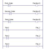
Fan.JPG

The "Fan" is Just a tag to hold the values, box1, box2, box3 etc is the input box on the screen, Fan_1, Fan_2, Fan_3 etc is you real PLC outputs
 
Last edited:
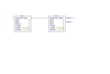
One way is to use a timer triggered sequencer (SQO) instruction. Since eight steps is the most on the spreadsheet you posted, create two eight element DINT arrays, one will contain the time for each step, the other DINT will contain the 8 bits of binary data for each step representing the states of the valves. Move the time for the matching step to a timer that triggers the SQO instruction.

Define another set of arrays containing all six profiles. Copy that to the array used by the SQO.
 
Last edited:
Hi... I'm not sure if your familiar boolean logic.if you have six elements and each element can only be either "1" or "0"... Put that into a truth table. use an integer register to store your Decimal value.... Use comparators function block to compare Decimal value. The rest is a walk in the park./
 
I am fairly new at PLC programming so im just thinking but to arrange them in order you might have to put a integer input next to each fan on the HMI to dictate the order. So you have fans 1 through 6 with the integer entry box next to them on the hmi. operator the order number into the box. so if he wanted fans 1 then 4 then 5 next to fan 1 he would enter a 1, next to fan 4 would be a 2, an next to fan 5 would be a 3. you can then link these to an integer array which you can go through finding the order.

Array positions correspond to fan number
Array values equal fan sequence
HMI:
Fan1 [int input] Fan2 [int input] Fan3 [int input] Fan4 [int input] Fan5 [int input]

So pattern 1,2,3,6,5,4
the array would look like

array[0]=1
array[1]=2
array[2]=3
array[3]=6
array[4]=5
array[5]=4

So you can have a sequence counter 1 to 6 and find which position has that value and execute that fans particular code. Increment sequence counter and repeat.

I guess you could record order of button presses and do the same but this might allow sequence editing. Also would have to have check code so same number not entered twice.
 
My perception of what is asked is: How to automatically sequence through up to six patterns.

This could be done by designating a code for each pattern then collecting the desired pattern codes in a file/array. Examine the first element's code and execute the corresponding pattern. When that's done examine next code and so on...

When the last pattern is complete, start over.

But, I could be wrong.
 
View attachment 20618

The "Fan" is Just a tag to hold the values, box1, box2, box3 etc is the input box on the screen, Fan_1, Fan_2, Fan_3 etc is you real PLC outputs

chavak ,

But the orders or not fixed like if he had given me the order I would follow like the ladder you have mentioned but he say the operator will click on any combination of fan (like he will select 1, 4,5 ,3,6,2) and the click start then the fans should operate in that sequence .:mad:
 
One way is to use a timer triggered sequencer (SQO) instruction. Since eight steps is the most on the spreadsheet you posted, create two eight element DINT arrays, one will contain the time for each step, the other DINT will contain the 8 bits of binary data for each step representing the states of the valves. Move the time for the matching step to a timer that triggers the SQO instruction.

Define another set of arrays containing all six profiles. Copy that to the array used by the SQO.

Any example please ????? How will use it with six fans ????

sqo.jpg
 
Hi... I'm not sure if your familiar boolean logic.if you have six elements and each element can only be either "1" or "0"... Put that into a truth table. use an integer register to store your Decimal value.... Use comparators function block to compare Decimal value. The rest is a walk in the park./

But this would not give me sequence is not it ????
 
My perception of what is asked is: How to automatically sequence through up to six patterns.

This could be done by designating a code for each pattern then collecting the desired pattern codes in a file/array. Examine the first element's code and execute the corresponding pattern. When that's done examine next code and so on...

When the last pattern is complete, start over.

But, I could be wrong.

Doug-p ,
No not automatic it depend upon the selection on the screen .
If it is automatic like the one for valves I would have programmed .But since the sequence depends up on the selector I am confused
 
I am fairly new at PLC programming so im just thinking but to arrange them in order you might have to put a integer input next to each fan on the HMI to dictate the order. So you have fans 1 through 6 with the integer entry box next to them on the hmi. operator the order number into the box. so if he wanted fans 1 then 4 then 5 next to fan 1 he would enter a 1, next to fan 4 would be a 2, an next to fan 5 would be a 3. you can then link these to an integer array which you can go through finding the order.

Array positions correspond to fan number
Array values equal fan sequence
HMI:
Fan1 [int input] Fan2 [int input] Fan3 [int input] Fan4 [int input] Fan5 [int input]

So pattern 1,2,3,6,5,4
the array would look like

array[0]=1
array[1]=2
array[2]=3
array[3]=6
array[4]=5
array[5]=4

So you can have a sequence counter 1 to 6 and find which position has that value and execute that fans particular code. Increment sequence counter and repeat.

I guess you could record order of button presses and do the same but this might allow sequence editing. Also would have to have check code so same number not entered twice.

This method would be done using C language but I need to do that in ladder it will take lot of steps but I will give a try .
 
In the example I posted, you need to have 6 input boxes on your screen which represent what fan number the operator key (number 1 to 6).

For eg. the operator key in the following order

Input Box 1 - "5"
Input Box 2 - "3"
Input Box 3 - "1"
Input Box 4 - "4"
Input Box 5 - "6"
Input Box 1 - "2"

PLC always run in the same order, - order 1 to 6, but it takes the data from the first input box, if it represent 5, then turn on fan number 5 when you turn on your first output, represented by Fan.[box1], It indirectly represent Fan.5 in this case. As Fan.5 connected to Fan_5 in the ladder, which in the actual output connected to Fan number 5, it runs

And for 2nd output, it turns on fan number 3 as the Second order runs Fan.[box.2] which is actually representing Fan.3.

In the example I only shows 3 fans, but you can easily expand it

Regards
_______
 

Similar Topics

Here's a question to the group. When will integrating devices in the Industrial Control world approach the simplicity of the Lego MindStorm...
Replies
2
Views
1,683
I'm after a quick and effective way to achieve the following with an FX series Mitsubishi: 10 registers, holding a variety of values, one register...
Replies
0
Views
2,291
Afternoon all, I'm working on setting up a large excel recipe table for porting updates through the Linx Gateway RTD/DDE function into my recipe...
Replies
2
Views
110
We are trying to poll data coming from a PLC for remote monitoring we have the IP address of the PLC and the default port number and the path is...
Replies
25
Views
568
Good morning. I'm doing a rehab and I need to recycle some part of the old code that won't change and that I need. This is a calculation that...
Replies
22
Views
1,357
Back
Top Bottom