Motion/ Force balance instruments

Theboss

Member
Join Date
Jun 2010
Location
Durban
Posts
159
Good day All,
I am curious to know why do these instruments try to maintain a constant pressure through the flapper/nozzle assembly eg I/P converter or pneumatic positioner.
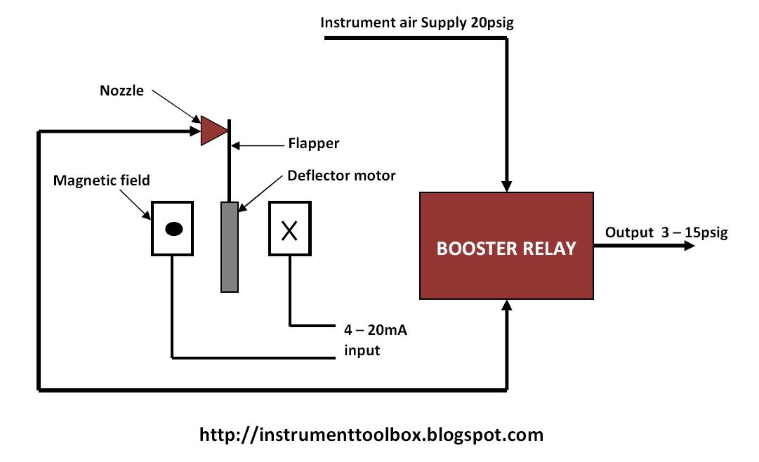
I/P converter :
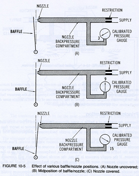
when a back pressure is reached, this back pressure is fed to the relay/booster. Then the bellows linked to an arm counter acts and allows the nozzle to move away from baffle, causing the back pressure to fall. So since the back pressure falls and back pressure is now reduced in relay/booster, how does the pressure to the actuator now increase to open the actuator /valve, when trying to open the actuator/valve.

Pneumatic positioner:
why is there a feedback spring/arm via a spindle/cam to counter act the 3-15psig, air that is been supplied to the diagram to shuttle the spool valve.

Correct me if I'm wrong, if there isn't any force trying to counter the spool valve movement, any value between 3-15psig will drive the actuator/valve fully open???

Please correct my understanding,it would be greatly appreciated.
Thanks in advance.
 
Last edited:
Diagram shows a basic I/P transducer.
The squares on either side of the flapper (circle on the left, X on the right) are a cross sectional view of the electrical coil surrounding the flapper.


I-to-P-Converter.jpg


The flapper creates back pressure in the nozzle, depending upon how far the flapper is from the nozzle, as shown in the graphics below:

nozzle-baffle-operation001-sm.jpg

The closer the flapper/baffle is to the nozzle, the higher the backpressure in the nozzle.

The further away from the nozzle the flapper baffle is, the lower the back pressure is in the nozzle.

The backpressure signal is a low level pilot signal to the volume booster, which supplies enough volume to 'follow' the pilot pressure.

An I/P does not attempt to hold a constant output pressure, it attempts to create a pneumatic pressure that is linear and proportional to the electrical input signal. If the electrical input signal holds steady, the flapper/baffle does not move, so the back pressure does not change, so the volume booster does not change its output. The pressure in a pneumatic actuator should hold steady, it's a closed, sealed volume that should not bleed or leak.
 
Am I correct about the pneumatic positioner operation and why there has to be a feedback arm to counter the 3-15psi input?
 
I'll take a pass on details of dumb positioners. Although I've sat through three or four power point presentations from different vendors of how a positioner works over the past 25 years, I can't remember any details because in the end, it doesn't matter how the internals work, what matters is the fact that a positioner is proportional controller, where the control signal is the setpoint and the position signal is the process variable so that a positioner corrects (or attempts to correct) for the difference between the demand setpoint and actual position, whereas an I/P does not.

If the process variable does not match the setpoint, the internal mechanics do whatever they do to create more or less pressure to force the position feedback to match the setpoint.

The I/P has no position feedback, it just pneumatically mirrors the electronic input signal. If sticktion prevents the valve from achieving the correct position, an I/P doesn't know that and can't do anything about it. A positioner knows the position and works to maintain setpoint (demand position from the main controller).

There's always some guru at the manufacturer who is dying to get an audience who will want to listen to what he has to say about how his positioner works. You might contact the manufacturer and try to find the positioner guru and ask him or ask for his power point. I can't imagine that if you can locate who it is, that he'd deny you his power point.

There's also some possibility that someone posted the power point on the web. Try searching for the brand/model and .ppt or .pdf and 'operation'
 

Similar Topics

Hi, Has anyone got any suggestions or ideally a working example of how to exchange data between a Lenze L-Force Motion controller (CoDeSys based...
Replies
0
Views
3,297
Bom dia, Estou com uma máquina parada algum tempo, meu servo funciona em modo manual, porém não funciona em automático. Meu equipamento e...
Replies
0
Views
58
Hi currently my existing PLC using AB motor & driver to spin production, however customer want to another set, if this possible we use different...
Replies
1
Views
205
I have always controlled servos in Rockwell motion using position loop. I have an application where one process will push against a servo...
Replies
3
Views
263
Hello Experts, I'm wondering if this has been done before if possible to create an Emulate file that have motion control axis? I tried to...
Replies
0
Views
142
Back
Top Bottom