OT:Transformer Conductor Sizing Question

Snyd1

Member
Join Date
Jun 2018
Location
there
Posts
225
Sorry, not really PLC's. I have been going around and around trying to get a solid answer to my question and not finding anything that really makes it clear to me.

I am working with a single phase 480V in 5kVA transformer with a grounded secondary providing 240/120V. ACME TB253014S

How would one go about properly sizing the secondary conductors?

PS: A previous designer has this as 14 on the primary, #6 for L1/2 and #10 for the center (Neutral/GND). it seems a bit much in my opinion for the loads
 
You size them according to what fuse you choose. Atleast here in EU

But if the Transformer is only capable of 10 Amps for example and you fit 50 amp fuses because thats the fuse you choose.... so you now fit 50 amp cable to fit the fuse......

That works well o_O
 
I calculate #6. (Assuming copper conductors)

(5000 / 120) * 1.25= 52.084 amps on secondary load conductors, code allows grounded conductor to be smaller.
 
Last edited:
You size them according to what fuse you choose. Atleast here in EU

Yes, I feel like this old design is missing a main secondary fuse/breaker across the X1 X4. As of now only the single 240V load is fused, then the individual 120V loads are fused.

The larger gage wire simply feeds the load breakers and all drop down to 14gage doesnt make sense to me.
 
Well, while this transformer is rated for 42A, it will put out 720A on short circuit.

rQx should have said
"You size them according to what fuse you choose, unless you choose a fuse 15 times bigger than you need."

There are also several other factors to consider such as conductors per cable, cables per bundle, cable arrangement, cable mounting method, cable temperature rating, ambient temperature, permissable cable temperature, cable length, permissable voltage drop. Environmental factors such as barometric pressure and dustiness can also influence the size of cable needed. For the earth there is also permissable earth impedance. You may also consider efficiency losses.
 
I calculate #6. (Assuming copper conductors)

(5000 / 120) * 1.25= 52.084 amps on secondary load conductors, code allows grounded conductor to be smaller.

K, so from what I gather from my reading on transformers. The #6 conductor chosen by the previous designer ahead of the load breakers would be protected by the primary side breaker. Then when it drops out of the breaker to 14 to feed the loads the 14 is protected by the load breaker..
 
i would size the conductors to the maximum current size for the output voltage.
then, size the fuse based on your needs. doing this allows for future current needs and you won't have to rewire the secondary.
james
 
Secondary conductor sizing
The ampacity of the secondary conductor must at least equal the rating of the device supplied by the secondary conductors or the OCPD at the termination of the secondary conductors [Sec. 240.21(C)(2)]. Assume the secondary conductors will carry the full capacity of the transformer continuously.

Step 1: Determine the rating of the device supplied by the secondary conductors at 125% of the secondary rating [Sec. 215.2(A)(1)(a)].

Step 2: Size the secondary conductors so they have an ampacity of at least the device rating supplied by the secondary conductors [Sec. 240.21(C)].
 
Conductor sizing is based on FLA. For your xfmr FLAp= 5000/480 = 10.4A;FLAs =5000/240 = 20.8A. In both cases, minimum conductor size is 125% of FLA. So you could use #14 on primary and #10 on secondary. This is minimum. Distance to feed and load will impact this ie voltage drop.
The #6 on the secondary comes into play if you use only 120V on secondary. Then your FLAs becomes 42A... This is based on Canadian code...the NEC must be similar. Your fusing must protect the wiring. If you use #10 on secondary, max fuse is 30A. You can choke it to something smaller. As a note, I would always wire and fuse to maximum to avoid a future re-wire if the load changes.
 
You size them according to what fuse you choose. Atleast here in EU

With all due respect, the above response is the reason fires happen and buildings burn down.

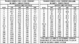
To find out what size wire to use I would begin by using the attached charts. After that requires more in depth electrical knowledge. Hire a qualified electrical contractor or engineer.

8373B621-29CC-4FF0-914C-D315ABE1B760.jpg
 
Conductor sizing is based on FLA. For your xfmr FLAp= 5000/480 = 10.4A;FLAs =5000/240 = 20.8A. In both cases, minimum conductor size is 125% of FLA. So you could use #14 on primary and #10 on secondary. This is minimum. Distance to feed and load will impact this ie voltage drop.
The #6 on the secondary comes into play if you use only 120V on secondary. Then your FLAs becomes 42A... This is based on Canadian code...the NEC must be similar. Your fusing must protect the wiring. If you use #10 on secondary, max fuse is 30A. You can choke it to something smaller. As a note, I would always wire and fuse to maximum to avoid a future re-wire if the load changes.

I suppose where I get hung up is with the dual voltages. Most of the load will be on the 240V side w/ ~3.7kW and only 1kW and change on the 120V. Distance is a non issue as the run is under 10'
 
With all due respect, the above response is the reason fires happen and buildings burn down.

To find out what size wire to use I would begin by using the attached charts. After that requires more in depth electrical knowledge. Hire a qualified electrical contractor or engineer.

I assume that you have the knowledge to choose the correct fuse, and then you size the conductor according to the fuse size. I also assume that you have the knowledge to select correct conductor for the fuse you are using. There is nothing wrong with this and no fire risk.
 
I assume that you have the knowledge to choose the correct fuse, and then you size the conductor according to the fuse size. I also assume that you have the knowledge to select correct conductor for the fuse you are using. There is nothing wrong with this and no fire risk.

You are correct that I know how to do it but you are assuming the other guy knows what size fuse to install. Put another way, which came first the chicken or the egg?

The first thing to know is what the xfmr is rated for.
 

Similar Topics

Folks, I am designing a control system for an industrial machine. Machine is 480VAC / 3PH powered. And I have a 480 / 120V transformer for control...
Replies
9
Views
1,396
Hi all, I know this sounds like a dumb question, but.....I'm thinking out loud...and maybe I shouldn't do that.... Upcoming project involves...
Replies
16
Views
4,157
Ignore - I asked this question already and found my answer.
Replies
0
Views
1,027
Hi all Where can i find this transformer ? Pri 480 v 3x 0.12 A Sec 400 v 3x 0.12 A 3 phase Type DTS 80 50/60 Hz
Replies
14
Views
3,570
Greetings experts, Can current transformers be used on the incoming mains (480, 3P) of a machine that has regenerative VFD's? Current...
Replies
9
Views
3,213
Back
Top Bottom