-- Electrical Design Question --

Esieli

Member
Join Date
Nov 2018
Location
Georgia
Posts
64
I have a weird situation here that I'm sure it's just something I'm overlooking. I would really appreciate any help!


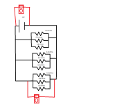
We have a battery that is powering a bunch of glow plugs. From my understanding the glow plugs are exactly the same as resistors.

I noticed it is dropping voltage from my 12V battery down to 7v or so.

Why would it not just stay at 12V?

The reason I'm asking is my glow plugs are not getting hot quickly enough.


Thank you!
 
If your drawing is accurate, that shows voltage drop on the conductors- they must be undersized for the distance they are run.
 
I have a weird situation here that I'm sure it's just something I'm overlooking. I would really appreciate any help!


We have a battery that is powering a bunch of glow plugs. From my understanding the glow plugs are exactly the same as resistors.

I noticed it is dropping voltage from my 12V battery down to 7v or so.

Why would it not just stay at 12V?

The reason I'm asking is my glow plugs are not getting hot quickly enough.


Thank you!

Hi, are you sure this is drawn correctly? Because according to Kirchoff's and Ohm's laws, you would have a total circuit resistance of 0.066 ohms and a current of ~ 181 amps. So you would need some serious cable for this set-up.
And as otherwise suggested, if this is a long distance, then even bigger cable would be needed. I've checked through these calculations twice, however if I've made an error, my apologies. Hope this helps.


You're correct. It is pulling a ton of amps.
 
If your drawing is accurate, that shows voltage drop on the conductors- they must be undersized for the distance they are run.


Thank you.

I tried increasing the size of the conductor and the number of conductors, but still didn't help it. It actually seemed like the more conductor I gave it, the more voltage drop I had.

I'm starting to think maybe it's the connectors I'm using.
 
Thank you.

I tried increasing the size of the conductor and the number of conductors, but still didn't help it. It actually seemed like the more conductor I gave it, the more voltage drop I had.

I'm starting to think maybe it's the connectors I'm using.

Yes, and with DC, connections are critical. Any resistance and everything changes. Just like with your car and the dirty battery cable scenario. Good luck and I wish you the best!!
 
Each of those glow plugs uses about 20A.

If you made a star connection with 3 wires coming out of each battery terminal, each one going to a group of 3 glow plugs and better without connectors then surely you would reduce the voltage drop a lot.
 
Keep in mind that the glow plugs probably increase in resistance as they get hot. To calculate ohms at temperature, you would need to measure the voltage across the plug, directly at the plug, and the amps going through the plug. Calculate to give resistance.


I seriously doubt that they will remain at 0.6 ohms when hot, unless it's internally shorted or something. It will still be pretty low, but higher than 0.6. It should give you a more realistic value to use when calculating required wire size, total amp draw, etc.


Is this a new setup? Or troubleshooting something that was working before? Do the glow plugs work as expected if you only try to power a small number at a time? Make sure your contactor can handle the amp draw as well; it will take a serious switch to handle that kind of current.
 
I've checked through these calculations twice, however if I've made an error, my apologies. Hope this helps.


I agree with your calculation: each triplet of 0.6Ω in parallel triple has the 0.6 divided by 3, so 0.2 each, and since there are three of those that 0.2 get divided by 3 again, so 0.066... in toto as saultgeorge suggests.


181 amps (actually 180 because 0.6 / 9 = 6/90 = 1/15)? That is one heck of a battery (or not;)); how warm are the conductors getting ;)?


As a diagnostic, can you measure the voltage drop (or resistance with no battery attached) across each piece of the conductor, and across any connectors?
 
Last edited:
Thank you.

I tried increasing the size of the conductor and the number of conductors, but still didn't help it. It actually seemed like the more conductor I gave it, the more voltage drop I had.

I'm starting to think maybe it's the connectors I'm using.

Increasing the wire size simply allowed additional current to flow, exacerbating the voltage drop on your battery. Likewise, any resistance from the connectors would increase the circuit's overall resistance, thereby reducing current flow.

Sounds like you have an inadequate source for the amount of power you want to consume.

This makes a lot of sense. Perhaps one would need say 2 or 3 12V batteries in parallel. This way you wouldn't lose so much voltage under load. I've had to do this with diesel engine applications in highway transports, marine and power generation use and heavy equipment. Most come from the factory with 2 large 12 V deep-cycle batteries with high current capacity. Maybe you already have it set up like this. Just a thought.
 
But the drawing showed the voltage measured at the battery is 12V. If that's true, then battery voltage sagging isn't the issue.
 

Similar Topics

I would really appreciate any help with this question and anything pointing to the NEC would be appreciated. Scenario: Let's say I have 6 motors...
Replies
6
Views
2,449
What's a good place to start for learning electrical design? I am always the end user so I can follow along machine schematics, etc. but I want to...
Replies
10
Views
3,880
Hi All, Can you guys please guide me which software are used most for designing the cabinets and cabling stuff for PLCs? For example, if I have...
Replies
1
Views
1,281
Hello everyone, For a project with 30 inputs, 30 outputs, including 2 servo motors and 4 AC induction motors on VFDs, a interlocking fence...
Replies
17
Views
4,302
Guys, I am curious what kinds of electrical controls design platforms you make use of. I mean: things like AutoCad Electrical, plain old AutoCad...
Replies
34
Views
14,787
Back
Top Bottom