1734-IE4S safety analog input issue/ not reporting value

g.mccormick

Lifetime Supporting Member
Join Date
Jul 2012
Location
IN
Posts
960
I ran into a strange issue the other day. System has been up and running for many months.

An analog input channel suddenly reported 0mA. I investigated assuming dead transmitter, wiring failure, etc.

I found that the transmitter was working and there was indeed a signal on the wire. The module lights for all 4 channels were red. I went on-line and the module status said NONE for major or minor faults. Also the module shows configured and Running.

The 4 channels on the module all had a status of 0 and the value for the channel was 0 for channel 0 (where transmitter is wired). I tested all 4 channels with a source and they all showed nothing.

Next, I changed the setting for one of the channels from 0-20ma to 0-10V and when I did, all of the channels starting working again. I was able to set the changed channel back to 0-20ma and everything stayed working. I found one other module that had the exact same behavior. It has all 4 channels as spares (the first effected module had one channel in use). I again had to change the configuration of a channel to get all of the channels reading again.

Neither module showed anything for faults, and both showed .RunMode = true.

Has anyone ran into this before?
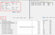
IE4s_NoErrors_Notworking.PNG IE4s_WorkingAgain.PNG
 
I ran into a strange issue the other day. System has been up and running for many months.

An analog input channel suddenly reported 0mA. I investigated assuming dead transmitter, wiring failure, etc.

I found that the transmitter was working and there was indeed a signal on the wire. The module lights for all 4 channels were red. I went on-line and the module status said NONE for major or minor faults. Also the module shows configured and Running.

The 4 channels on the module all had a status of 0 and the value for the channel was 0 for channel 0 (where transmitter is wired). I tested all 4 channels with a source and they all showed nothing.

Next, I changed the setting for one of the channels from 0-20ma to 0-10V and when I did, all of the channels starting working again. I was able to set the changed channel back to 0-20ma and everything stayed working. I found one other module that had the exact same behavior. It has all 4 channels as spares (the first effected module had one channel in use). I again had to change the configuration of a channel to get all of the channels reading again.

Neither module showed anything for faults, and both showed .RunMode = true.

Has anyone ran into this before?

No - I have not seen anything like this.

I assume that no one else has either since the view count is above 100

But I've added it to my 'If nothing makes sense, check here' list
 
No - I have not seen anything like this.

I assume that no one else has either since the view count is above 100

But I've added it to my 'If nothing makes sense, check here' list

Well ****. I also assume no one else has seen. If this comes up again I will be sure to let you all know. Very strange for sure, luckily my application is not production but instead a testcell that wasn't even running when the issue arose.
 
That's interesting behavior. I searched the knowledgebase but didn't find anything that directly addresses it. There is a tech note (Access Level: TechConnect) that talks about how the channels respond to faults and seems to be summarizing the manual. It's weird that it's a TechConnect only article, but there you are.
https://rockwellautomation.custhelp.com/app/answers/answer_view/a_id/1059326/loc/en_US


It refers to the manual, which describes the channel status lights and how they behave in Appendix A...and refers to Appendix B to configure a MSG instruction to retrieve the error codes:
https://literature.rockwellautomation.com/idc/groups/literature/documents/um/1734-um013_-en-p.pdf


All that to say...I wonder if you could implement the MSG instructions to gather more data on what's happening.
 
Thanks Joseph & Jstolaruk for replying.

Forgive me, but can you tell me what the MSV & GSV instructions are please?

"The Get System Value (GSV) instruction will retrieve a system value status from the controller that can update a specified destination tag with that value."

"The MSG instruction provides an easy way to establish communication between two Allen Bradley PLCs."
 
Normally I'd use a GSV instruction to get module status, but the user manual specifically says to use a MSG instruction and doesn't even mention a GSV. I'm not sure how I'd configure the GSV or interpret the results for something like this and it isn't documented in the user manual (it may be elsewhere).
 
Normally I'd use a GSV instruction to get module status, but the user manual specifically says to use a MSG instruction.......
...further complicated that the MSG instruction use was in the SmartGuard Controller section of the manual. Sounds like a good test bench project, fault the module and then see if the fault status can be sucked out of it. o_O
 
Thanks Jstolaruk,

Unfortunately I am only a maintenance electrician & have very little knowledge of PLCs and the programming software etc. lol

The faulty module has been running along side similar ones for many years, each one supplies a 4-20mA loop to 4 off temperature transmitters.
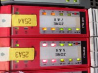
The suspect module is showing 4 input lights solid red, 4 lights green and PWR light green.

Upon checking (and comparing to the working module next to it) I have found that the 24vdc is not present (even though the PWR light is green)
I have attached a pic.
I have checked the obvious, wiring etc but no luck.

20230714_113228.jpg
 
I've never even heard of the SmartGuard controller. I just looked it up and it was discontinued last year.


The appendix where I found info about MSG instructions is titled "Get I/O Diagnostic Status from Modules in Logix Systems".
 
Thanks Jstolaruk,

Unfortunately I am only a maintenance electrician & have very little knowledge of PLCs and the programming software etc. lol

The faulty module has been running along side similar ones for many years, each one supplies a 4-20mA loop to 4 off temperature transmitters.
The suspect module is showing 4 input lights solid red, 4 lights green and PWR light green.

Upon checking (and comparing to the working module next to it) I have found that the 24vdc is not present (even though the PWR light is green)
I have attached a pic.
I have checked the obvious, wiring etc but no luck.
Understood. I believe the next option is to replace the module and it should require the software to configure the new modules safety connection to the processor.
 
...
The suspect module is showing 4 input lights solid red, 4 lights green and PWR light green.

Upon checking (and comparing to the working module next to it) I have found that the 24vdc is not present (even though the PWR light is green)
I have attached a pic.
I have checked the obvious, wiring etc but no luck.


PWR being green means that field power is present...but you don't see it there...weird. Do the voltage readings match the other modules? Is it possible to swap the module with another and see if the problem stays or follows? You'd have to power down the 1734 chassis, of course.
 
I've never even heard of the SmartGuard controller. I just looked it up and it was discontinued last year.

I used it a couple of times, it filled the gap between a non-safe processor and the need for something more than the simplicity of a simple safety relay. Didn't know it was dis-continued, thanks for the update.
 

Similar Topics

Hi all. I'm currently working with a safety guardlogix 1734-ie4s in which it keeps losing its channels i.e. red lights and fault bits. The...
Replies
2
Views
2,501
Hi everyone, new to forum. Since very long time i having issue with 1734-AENT module, after some period of time its keep stuck in error (simmilar...
Replies
7
Views
330
I am trying to use the 4-20 mA signals from a device whose user manual says that it outputs "isolated 4-20 mA". I only have spare PLC inputs in a...
Replies
3
Views
219
Hello The plant is running and there is no shutdown nowadays therefore I can add 1734- AENTR and its card while PLC is in Run? I do not wanna...
Replies
8
Views
343
Hi all, This is my first time working with a 1734-IE2C analog module. I am tasked with wiring the flow meter into the analog card and the OEM is...
Replies
2
Views
160
Back
Top Bottom