PID level control of sequential pumps

I agree w/Saffa and would add that the operator won't care about flow pacing as much as he wants the discharge flow to be adequate for pipe scour. Another unmentioned concern are the check valves slamming if the accel + decel times are extreme.
 
Is that 1gpm? and the tank gain is something like 17ft/30kgal?

It is 1 something / sometime. Just for example. I don't know the parameters of the process, so I just made a model according to your suggestions regarding control.
To demonstrate control curves that seem strange to me.
 
While I appreciate all the responses and apparent interest here, I think everyone is way overthinking this and this discussion has gotten in to the weeds a bit. There are a lot of requests for additional info to answer questions I never asked, while the ones I did ask remain mostly unaddressed.

First, some clarifications, mostly repeated info at this point, since I know there will be a slew of unrelated questions otherwise:

1. The system was professionally designed by a firm with a lot of experience in the field, so I am sure everything is designed and sized correctly, and if it isn't it's not my problem. I do not know the specs of the pumps, other than that they are 150HP and they are all the same. I have requested this info several weeks ago, but the contracting company is not very responsive, so I am proceeding anyways. It's really not that big of a deal. I am assuming with fair certainty centrifugal pumps and a 20% minimum pump speed. Also, the site is under construction and nearing completion, so no change requests will be made, certainly not by me.

2. The process control description is very basic, but as mentioned asks for PID control of the 4 pumps which will be sequentially enabled when they are in their start/stop windows, which are ascending by level. All 4 pumps will have the same target level SP they are trying to maintain. I have mentioned some values in an earlier post, if anyone cares. That's all the spec says. However, the specs directly call for PID control and the specs are gospel, so that is what I am contractually obligated to deliver. As @Saffa mentioned, I can simply set I or D values to 0 if needed, but this is really a tuning issue, which will be handled at startup and I don't anticipate any difficulty with it.


Now, if I could redirect everyone back to the original questions, I would appreciate it.

1. Is it worthwhile to use a PIDE block here over a regular PID block, considering I will need to spend a little time familiarizing myself with it and what useful options should I look for (since there are so many)? I am leaning towards using the PIDE just on the basis of rate change limits and bumpless handover, but that brings my next question.

2. What are recommendations between using the PIDE's built in rate of change limiter vs using an RLIM external to it? Any practical difference? My initial plan is to use both, with the internal limiter set to be a little faster for more responsive control and using an extra RLIM on pump start that brings it up to speed a little slower before bypassing it.

3. From a control strategy overview, any high-level recommendations on setting up the control? My plan is a single PIDE block (potentially tuned to PI), when adding pumps ramp them up at a fixed rate until their speed matches the PIDE CV speed (which will be falling due to the new pump) and then hand them over to the PIDE control which will be scaled to the number of running pumps.
 
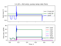
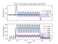
My P-only-lead/I-only-lag approach is a bust.

I built a model, with empirical system tuning; I'll leave proper analysis and tuning to others.

Each pump can deliver 10kgpm at 100% speed; minimum pump speed is 20%; to simplify I used the ideal case for what @Saffa said, i.e. static pump differential head only; tank gain is 17ft/13kgal.

It's very sensitive to pump ramp rates, since that changes the overall system. Anything below a few percent per second does not work well, and I think reasonable ramp rates might be in the 10-25% per minute range (0.17-0.4 % per second).

I got so-so control with a ramp rate around 20%/s (first image), although that ramp rate could be two orders of magnitude too high; at 1%/s (60%/min) the system is not stable (second image).

These test cases start at 6kgpm inflow (load), change load to 3kgpm, back up to 6kgpm, then back to 3gpm, then a big jump to 29kgpm (increase of nearly 90% of three pumps' capacity), then back to 6kgpm.

The 6-3-6-3 changes are handled well by the P-only lead pump.

The big jump is where the trouble is; it even brings in the fourth pump, so operation during maintenance could be problematic.

pid_lead_lag_ramp_20pct-Hz.png pid_lead_lag_ramp_01pct-Hz.png
 

Attachments

  • pid_lead_lag.zip
    3.2 KB · Views: 2
@drbitboy, @skyfire. I am keeping it simple. No PIDE is required. Just some range checks. The drives can take care of the ramping up and ramping down.


I can make make it more precise by having an outer PI loop that sets a reference flow rate than then must be tracked/satisfied by the up to 4 pumps, each having its own PI control. So this would be cascaded loop type of system. Again we do something like this for four corner presses where there is a total tonnage that must be maintained and it sets a position of velocity command to the four corner actuators so they stay aligned even if the load for each corner actuator is different. This avoids skew. It works well but it is overkill for tank level control that doesn't need to be precise.
 
The level setpoint they are trying to maintain for the PID block is 8.5ft. The start SP for the Lead Pump is 9.5ft and stop is 7.5. For Lag1, start is 9.8ft, stop is 8ft, and so on. Basically, the lead pump turns on at 9.5ft then tries to maintain level at 8.5ft. If the Lead pump can't keep up, Lag1 comes on at 9.8ft, and then they try to maintain 8.5ft, and so on. The pumps have a minimum speed requirement per the manufacturer, which I assuming to be 20% for now
If

  • those numbers (bold italics above) are not typos, and
  • the start level is for 100% pump speed, and
  • the stop level is for 20% pump speed,
then the PIDE rate limiter won't work because those start/stop ranges are different i.e. a CV rate of a single PIDE driving the Lead pump at a rate limit of X would be a rate limit of X/0.9 for the Lag1 pump.

Also, the feasibility of this control scheme comes down to design rate limits and the tank gain. If the pump rate limit is something like 10-25%/minute, and the inflow load increases sharply (whatever that means) so the level starts rising and hits the next lag pump start trigger, then it is only 3-4 inches to the start trigger for the lag pump after that, and a 10-25%/minute ramp rate may not be enough for the first lag pump to stem the level rise before the second lag pump is triggered. It's not the end of the world, but I suspect in most situations this arrangement will gravitate to running all available pumps.
 
@drbitboy, @skyfire. I am keeping it simple. No PIDE is required. Just some range checks. The drives can take care of the ramping up and ramping down.


oh I agree.

If it uses a PID or PIDE block to implement the scaling so that contractual obligations are met, then who cares?

I don't see any options in PIDE that are not either available in PID or useful in this application, so I don't think it matters which instruction is used.

Given that the P-only/I-only scheme went down in flames, I agree with @Peter here: P-only is almost certainly going to be good enough, as several of us have written long ago in our responses to this thread.

P.S. I'm still curious about the magnitude of the rate limiting, the static pressure rise, and the expected flow rates.
 
3. From a control strategy overview, any high-level recommendations on setting up the control? My plan is a single PIDE block (potentially tuned to PI),
That will work but it is much more complex than what I suggest. Tank level control does not require an integrator unless the level must be maintained precisely. You are must making things harder on yourself.

when adding pumps ramp them up at a fixed rate until their speed matches the PIDE CV speed (which will be falling due to the new pump) and then hand them over to the PIDE control which will be scaled to the number of running pumps.
Do you mean speed or flow? You better mean flow. Speed doesn't fill the tank, flow does.

Otherwise, this plan will work too but can't the ramp up and ramp down be handled by the soft start drive? Again, you are making it harder on yourself.

A question I have. Once you decide to use a PI control, how fast is the PI control going to respond to changes in the outflow? This is a point that drbitboy brought up. How will the integrator help? The integrator time constant determines how low it will take for the integrator to wind up or down to the new integrator value.

How will you handle starting and stopping pump as a function of the outer loop's requested flow rate? Now you are getting into the more complicated version of control I mentioned above.
 
Possibly off topic
I Please to excuse me for such noob question:
PIDE formula:
CV(n) = CV(n-1) + Kp * delta_E + Ki*E*delta_t + Kd*(E(n) - 2*E(n-1) + E(n-2))/delta_t
is it correct?

If Kp=1, Ki=0, Kd=0, and for example SP = 8.5 PV(n)=PV(n-1) = 10

What is the value of CV(n) ?
 
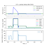
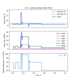
  • Model similar to OP's Post #8 configuration ...
  • With P-only control as suggested by @Peter Nachtwey and others since the first few replies to this thread:
    • minimum speed reference = 20% at 8.4ft level;
    • maximum = 100% at 9.0ft;
    • that one speed reference goes to all pumps.
      • Implemented with a Python class similar to a Logix PID instruction "to meet contractual obligation,"
        • but KP = 1.0, so the model would behave identically with the SCL instruction.
  • Pump 1
    • starts running by ramping from zero speed when level exceeds 9ft;
    • stops running (drops to zero speed; no ramp) when level drops below 7.5ft;
    • in between those levels it maintains its previous run state (Start/Stop Circuit pattern)
  • Pump 2 starts at 9.3ft, stops at 7.8ft.
  • Pump 3 starts at 9.6ft, stops at 8.1ft.
  • Pump 4 starts at 9.9ft, stops at 8.4ft.
  • Three pumps are available in the image on the left; four pumps on the right.
  • Green line in the middle plot is inflow (load): 6kgpm; 3; 6; 3; 29; 6; 2.1.
  • Ramp rate of 2%/s may be unrealistically high;
    • lower ramp rates have larger excursions and more oscillations;
    • vice versa for higher ramp rates
      • 20%/s has a max level of less than 9.9ft so it doesn't even start the last lag pump.
skyfire_3pumps.png skyfire_4pumps.png
 
Possibly off topic
I Please to excuse me for such noob question:
PIDE formula:
CV(n) = CV(n-1) + Kp * delta_E + Ki*E*delta_t + Kd*(E(n) - 2*E(n-1) + E(n-2))/delta_t
is it correct?

If Kp=1, Ki=0, Kd=0, and for example SP = 8.5 PV(n)=PV(n-1) = 10

What is the value of CV(n) ?

Yes it's essentially correct.

CVn above will be equal to CVn-1.

TL;DR
Code:
ΔE[sub]n[/sub] = PV[sub]n[/sub] - PV[sub]n-1[/sub]
    = 10 - 10
    = 0
 
CV[sub]n[/sub] = CV[sub]n-1[/sub] + K[sub]P[/sub] ΔE
    = CV[sub]n-1[/sub] + K[sub]P[/sub] 0
    = CV[sub]n-1[/sub] + 0
    = CV[sub]n-1[/sub]
That formula is not limited to PIDE

D-term may use PV instead of E, to prevent changes in SP from generating D-driven response.


Here is that PID equation implemented in a Python class:

def update(self,PV):
"""PID equation: incremental (a.k.a. "velocity") form"""

### - Error portions of P, I and D terms, in percent units
Ierr = self.calc_Error_pct(PV) ### Error; E(n); PV-SP or SP-PV
Perr = Ierr - self.last_error_pct ### delE(n) = E(n) - E(n-1)
Derr = Perr - self.last_Perr_pct ### delDelE=delE(n) - delE(n-1)

### - Apply PID equation, clamp result, percent units
self.CV_pct = self.CV_pct_clamp(self.CV_pct ### CV(n-1)
+(self.Kp * Perr) # +P
+(self.Ki * Ierr * self.deltaT) # +I
+(self.Kd * Derr / self.deltaT) # +D
)

### - Save error terms for next update
self.last_Perr_pct = Perr ### Will be next update's delE(n-1)
self.last_error_pct = Ierr ### Will be next update's E(n-1)

return self.calc_CV() ### Scale CV_pct to output range


I'll leave PV-based D-action for another day, or simply adjust delE(n-1) in the class method that changes the SP.
 
Last edited:

Similar Topics

How can I connect PID Output to a valve. In ladder logic program is there any logic do I want to add between valve and PID? PV=SP What will be the...
Replies
7
Views
409
Have a level control application that consists of a small chamber relative to the size of the incoming and outgoing pumps. I've done this type of...
Replies
6
Views
3,586
Good morning, I have a question and I don't really know what you would call this.... I have 2 tanks which I need to control the level or froth...
Replies
14
Views
7,756
Hi friends I have a L24ER-QBFC1B in a Level Control that you can see in the picture. Tank1 is the process tank. Level sensor is the process...
Replies
4
Views
3,047
I am working on a CIP project. There is a tank which is about 1500L. We need to keep the water volumn inside the tank to be SP:200L. The control...
Replies
17
Views
10,832
Back
Top Bottom