help on CMP and MOVE?

sutton

Guest
S
hi guys,

i'm now into my second PLC project. My first project was fine and thanks for helping me through.

now in my second project i had encounter some problems. it's using a Human Machine Interface, Mitsubishi F940G0T-E to communicate with PLC Mitsubishi FXon. well, by using HMI i will need to use data register which i have yet to use in my first project.

I tried to use Compare and Move function in a state of my program but i got stuck at the moment. Here is the logic process i'm trying to solve:

1. No. of operation cycle determined by counter setting in HMI.
(I managed to solve this one using counter with data register, fine.)

2. Uni-directional and bi-directional sequence is selected by HMI.

3. If bi-directional sequence is selected,
-during odd number of cycle, the motor is 'clockwise state'.
-during even number of cycle, the motor is 'counter clockwise state'.

4. If uni-directional sequence is selected,
-all the cycles are 'clockwise'.

Please tell me if Move and Compare functions are the right way to solve this logic? or is there any other way. Thank you.

sutton
 
Hi Vetteboy,

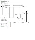
thanks for reply. well, here's a structure of one of the twelve stations in my machine. sorry it's badly drawn here. It basically tell us how a station function by controlling the HMI.

thank you.

sutton
 
Hi Vetteboy,

thanks for reply. well, here's a structure of one of the twelve stations in my machine. sorry it's badly drawn here. It basically tell us how a station function by controlling the HMI.

thank you.

sutton
 
Hi Vetteboy,

thanks for reply. well, here's a structure of one of the twelve stations in my machine. sorry it's badly drawn here. It basically tell us how a station function by controlling the HMI.

thank you.

sutton

:(
 
Sutton,

Sounds like you are on the right track. This would be simpler to do if you were using a fx2n because you could use inline compares instead using the compare function. Just remember when you use the compare function you use three consecutive devices even if you only care about one.
If you are having trouble figuring out how to tell a difference in your program between a odd count and even one way would be to divide your count value by 2 and move it into a data register (let's say d10)
your remainder will be stored in the next data register in this case d11. So if your count is even d11 will be equal to 0. If your count is odd d11 will be equal to 1. There probaly are other ways to do this. I am a programming rookie also. I'll let you think about this a little while. I will be glad to post example code if you need.
 
getting closer

tlvaun,

thank you for reply. it seems my idea is going on the right direction. it's great you tell me to use divide function. i will have a go later. however, my number of operation cycle is adjust using HMI touch screen. is that still possible of using the way we are doing?
Please show me how you work out the code, thank you!


sutton
 
I dont think you need to use COMP & MOV at all

You said you were using state programming.

Set up 2 separate state routines;
One for uni direction and the other for bi-direction.

The uni direction state routine can sequence with a counter at the end to start the sequence again until the preset count is reached.

The bi direction state routine can change the direction after each stage until the counter preset is reached again.

The hmi can set which state routine to use.
 
Sutton,
Until Goody pointed it out I didn't realize you were using stl programming. This was my idea for figuring out the direction of the motor in bidirectional mode.


m8000 (always on bit)
--ll----------------------(div d5 k2 d10) I assumed d5 was your count
l
l-----------------(cmp d11 k0 m10)
m11(d11= 0) (bidirectional pb set)
--ll-----------11----------------(counter clockwise state)

m10(d11= 1) (bidirectional pb set)
--ll-----------11-----------------(clockwise state)
(unidirectional pb set)l
--ll--------------------


This should work, but remember I said I was a programming rookie. Goody is
probaly the most knowledgable person on this site when it comes to Mitsubishi so maybe he'll post again and we'll both learn something.
 
Not quite right..

Hi Tlvaun,

thank you for your example code. However, I think we'd got a problems by doing that way. I guess my explanation is confusing!

well, im using ladder diagram actualy. The 'state' i mean earlier on is process state. sorry for wrong use of technical word.

right, back to the code. Let's make d5=3 operation cycle.

The machine is suppose to spin 'clockwise' during it's first operation cycle, then 'Counter Clockwise' during the second, and 'clockwise' again on the third.

By using your example code, all the operation cycles will be in clockwise state. i tried some other ways but end up with the same result!

well, is there any other idea, anyone please help! thanks!

oh yea, i'm a 3 months rookie in PLC. and it's my first job.
 
Sutton,

I tried code on my test plc (fxo). It worked as I had imagined although I may have not understood what you are trying to do. Try posting some of your code and I'm sure some others will be willing to help.
 
Sutton, Tivaun's method should work fine.

You will have either one or the other M relay on while the count is odd or even.

In the real world though, I would not use this method.

One reason, it is hard to follow (for someone else) what exactly is reversing the motor. (in this case a remainder after a divide)

What about if power is temp lost, the counter may reset to zero, the data register also.

An odd/even sequence is just a 2 state repeat cycle.

You need to do it with a memory relay (or 2)

First cycle, memory relay 1 is set, second cycle memory relay 2 is set and memory relay 1 is reset.
(if these are made retentive, the last state will be remembered through a power cycle)
This continues until the 'batch' counter preset is reached.
 
Last edited:
Alternate state

Hi Tlvaun and Goody,

Sorry for late reply. My senior blocks my access to Internet. How silly!

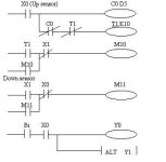
I had solved my problem by using Alternate function.
Y1 – Clockwise state when ON. - Counter clockwise when Off.
M10- DC control valve ON, motor goes down. M11-DC control valve OFF.
Y0 is used as interval time for motor to stop and change direction. (Since I’m using Induction motor)
Please note T1is used to control Alt function. Take away T1 and you will see Alt will not function rightly.
I will try to test your code again later. Sorry to confuse you. Thank you anyway!

sutton ;)

autodeb.jpg
 
Good jobs!

hi Tlvaun,

I had just tested your code. It works very well. Thank you very much for your help. I didn't notice you were actually comparing the divided remainder. THanks a lot! talk to you soon. :)


sutton
 

Similar Topics

Hi everyone. It’s been a while since I posted anything but I am hoping one or more of you can help me with this small problem. I am working with...
Replies
6
Views
8,858
OMRON PLC C200HX or CS/CJ . This PLC manual said that CMP(20) command don't support @CMP(20) type . but I can use CXP3.0 edit @cmp(20) and...
Replies
7
Views
5,807
I'm fairly new to Rockwell software, I've had some basic training in the past but nothing too advanced. My company and I use Reliable products for...
Replies
11
Views
271
Hi all I need help on this As in my project used Schneider TM241 controller. Now I want to communicate Elite energy meter with controller by...
Replies
3
Views
150
Back
Top Bottom