RSlogix Better way to control outputs in sequence

Off but related topic, if you are using an AC/DC transformer to control the trains, you can connect the AC side of it to a PowerFlex 4 series drive and control the speed. I was surprised at how well it worked and how smooth it was.


Lionel trains use an AC transformer output for speed. I modified the Lionel transformer so I can input a 0 - 3.3VDC to the throttle control. The analog output is 0-10VDC so I made a voltage divider so the output cannot exceed 3.3VDC to the transformer.


Mike
 
From post #7:

I do have a real input I:0/1 which is an actual relay start-stop circuit that is for manual or automatic mode. In manual mode I have control of the switches for track power and turnout switches. When I go to automatic mode, it energizes relays and control is turned over to the PLC.

I can make that the first condition of each rung so all rungs are false if the layout is in manual.
Mike

I'm rusty but, a possible alternative to adding a condition to each rung might be the MCR instruction - resets non-retentive outputs.
 
Yes you should change to integers, I prefer it that way anyway.

For handling multiples, I do 'request bits';

e.g.

seq. step 2 requests track power, OTE bit B3:0.0
seq. step 5 requests track power, OTE bit B3:0.1
 
I was thinking of using an integer to control the outputs since I would need far more then 16 bits of a B3 value. This way a non-zero value say in N7:40 would energize an output. I need to control 6 outputs this way (the track power areas)


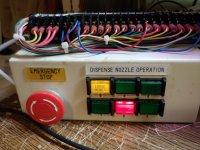
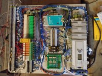
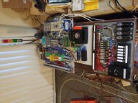
The button box shown has the safety circuit (E-stop with yellow reset button) and the "Stop" and "Start" buttons are for manual or automatic control. This is a basic stop-start relay circuit. In manual mode the engineer control panel (where you see the six power switches and the Lionel track switches) has control of the layout. I can operate the layout like any other model railroad. Once I go to automatic mode, the relays on the panel close and control is handed off to the PLC.


My plan is to have one ladder routine execute upon entering automatic mode, it will energize the main line track and detect the train on the track and make sure its moving forward. Then I will set a variable to indicate that is done and that routine will not execute again. The main ladder program will simply wait until I press a button on the HMI to tell it what I want to do next. So four of the outputs will be left on.


This main routine will also monitor the blocks that detect the train on the layout to make sure it is still moving and did not stall or derail.


So when I execute another routine, that requires manipulation of track power, it would just write a zero into that integer to turn it off. I can write in progressive larger numbers so for debugging purposes, I can see where the last write to energize the track power came from.


Mike

0120201956 (Medium).jpg 0205201650 (Medium).jpg 0211201705 (Medium).jpg
 
Yes you should change to integers, I prefer it that way anyway.

For handling multiples, I do 'request bits';

e.g.

seq. step 2 requests track power, OTE bit B3:0.0
seq. step 5 requests track power, OTE bit B3:0.1

Have a sub-routine called outputs

In it have
----XIC B3:0.0----- (OTE O:0/9)
|--XIC B3:0.1--|

etc


Yes I like to call them Requests too.


First of all,
Latch bits are a touchy subject, but generally don’t ever use latch bits (or set-reset bits) unless you WANT the information to stay during a power up.
Always use a sealed in coil that drops out if power is removed. That way the sequence will always have to start from the beginning.

Secondly,
You may benefit from this website: Patterns of Ladder Logic

It is mostly RS-logix 5000 based, but the same principals apply. With just those standard patters, you can make almost anything happen.

As far as outputs are concerned, I always have a routine at the end of my programs that is JUST the outputs, right in address order. Use the sequence bits to drive them in auto mode. Use a push button to drive them in manual mode. The first thing you usually want to find in a program is what is driving the output, so make them easy to find. Don't bury the outputs in the other logic.


Oh cool find, on that link
 

Similar Topics

I have a little bit of experience with Allen-Bradley. I have a Micrologix 1500 (RSLogix 500) and a PanelView Plus 7 (FactoryTalk View Studio ME)...
Replies
2
Views
80
I am completely stuck on building a ladder program that requires a start button to be pressed 3 times to turn on motor 1. Then motor 2 starts...
Replies
20
Views
521
buen dia. tengo una falla al pasar los tags de mi plc SLC 5 0/4 a mi panel me aparece un error Problem writing value " " to item <tag name>...
Replies
1
Views
73
First off, I'm a hobbyist-level programmer, and this program isn't controlling anything anything that could even remotely be considered "life...
Replies
18
Views
502
Back
Top Bottom