Schematic Help

samvivi7

Lifetime Supporting Member
Join Date
Apr 2016
Location
NJ
Posts
50
Hey Everyone,

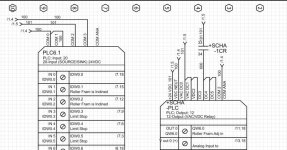
I need a little help with the attached schematic.

On the Input card, I have;
COM 0 and COM1 to 0VDC --- other side of the sensor is connected to +24 VDC
COM 3 the same way
COM 2 the opposite

On the Output card;
VDC and NEUT for the card power

DC0 --DC2 are group power

DC3 --DC5 are group power only when 1CR is energized

Do i have this right???

Thanks for any help
Capture10.jpg
 
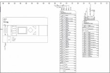
outputs are all relay so you can do what you like, and yes the relais is correct.
however the inputs i am not sure depends on the input type card.
 

Similar Topics

Hello, fairly new to plcs I’m tasked with installing a PE to a micrologix1200, in the attached picture I/14 is the PE I’m installing it’s going to...
Replies
6
Views
942
This is my first IO-Link project. I am having trouble figuring out how to draw this in ACAD-E. How to show the system as well as the wiring to...
Replies
6
Views
1,753
There are so many different ways to tackle the first sheet of the schematics. I've seen some people with a cover sheet, followed by several...
Replies
13
Views
2,598
Which Style to you expect to see on a drawing? Which style to you prefer? Keep in mind this being used on very large projects Style 1 Style 2
Replies
21
Views
6,733
Hello, A couple of questions regarding NEMA schematics and terminal block labeling. 1) I am familiar with the DIN designations for components...
Replies
4
Views
3,100
Back
Top Bottom