Question from a newbie

Rocguy

Member
Join Date
Dec 2016
Location
Chicago
Posts
48
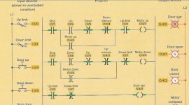
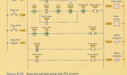
Hello guys, I am now taking a PLC class. In my textbook we have a diagram for a garage door opener. This is using AB SLC 500. The attached page is straight from the textbook. It appears to be showing that the door is currently ajar. Rung 3 is completely true and the red door ajar pilot light is on. What I don't understand is... in rung 1 the "up" LS at address I:3/0 has an XIC instruction that appears to be true. I don't see how the LS can be closed if the door isn't fully opened. Rung 3 shows the same thing.
The description at the top says it uses a normally open-held closed up limit switch. What is holding it closed if the door isn't fully opened? Is it a mistake in the book or, a mistake in my head?

Garage door opener PLC scan.jpg
 
Ok, this is a case of bad description and I run into that many time before. Call a switch Normally-Open or Normally-Closed doesn't tell me jack.

I would change the description of the the two limit to:

The UP-Switch would open when the Door is all the way up.

The Down-Switch would close when the Door is all the way down.

Or

If you just want to save on words, one should always name the PLC I/O tag based on the energized state:

UP-Switch in this case should called "NOT-All-The-Way-Up-Switch" and the Down-switch called the "All-the-way-down-Switch"
 
My eyes... make the pic bigger or type out the rungs.

Ok, this is a case of bad description and I run into that many time before. Call a switch Normally-Open or Normally-Closed doesn't tell me jack.

I would change the description of the the two limit to:

The UP-Switch would open when the Door is all the way up.

The Down-Switch would close when the Door is all the way down.

Or

If you just want to save on words, one should always name the PLC I/O tag based on the energized state:

UP-Switch in this case should called "NOT-All-The-Way-Up-Switch" and the Down-switch called the "All-the-way-down-Switch"

Above the input devices themselves, it says "shown in unactuated condition" If I understand that correctly, each switch would then close when the door hit it. Rung 2 has NOT logic for the down limit. So when the door closes all the way, it should close the LS and cause that NOT instruction to become false. This would disable the down motor. My brain is telling me I should see the same logic for the up LS in Rung 1 and 3.

What am I not getting here?
 
A quick glance at the logic says to me that the Up_Limit switch should be a normally-closed switch, which is opened by the door being fully open.

Then the third rung would make sense - it is not open, and not closed.

Having said that, and the logic presented doesn't support it without modification, I would suggest that the Down_Limit should also be a normally-closed switch, which is opened by the door being fully down. Normally-closed switches at both ends of the door travel would safeguard against a "wire-off" situation from either switch.

It does amaze me how these errors, inconsistencies, and bad design practices find their way into published text-books for classes that people pay for.

EDIT : Yes, in a nutshell, the logic and documentation do not match !
 
Last edited:
A quick glance at the logic says to me that the Up_Limit switch should be a normally-closed switch, which is opened by the door being fully open.

Then the third rung would make sense - it is not open, and not closed.

Having said that, and the logic presented doesn't support it without modification, I would suggest that the Down_Limit should also be a normally-closed switch, which is opened by the door being fully down. Normally-closed switches at both ends of the door travel would safeguard against a "wire-off" situation from either switch.

It does amaze me how these errors, inconsistencies, and bad design practices find their way into published text-books for classes that people pay for.

EDIT : Yes, in a nutshell, the logic and documentation do not match !

Now that makes much more sense. I also thought "it makes more sense if a switch opens when you want to kill the power to something but, I am a beginner to PLC so.....
 
Now that makes much more sense. I also thought "it makes more sense if a switch opens when you want to kill the power to something but, I am a beginner to PLC so.....

It's called "fail-safe"

It is sad that the "teachers" aren't instilling confidence with their poor material...

Where's the timer that says "it's taking to long to open or close this door"...? Without it the motor will run forever waiting for a feedback that it never gets.

Where's the motor over-current input that kills (and reverses for a time) the motor before it crushes a child, a dog, or a cat ...? (I believe it is now standard for electric windows in cars to have this functionality, surely the same applies to garage doors ...).

And for anyone who thinks this is going OTT for course material, the sooner budding engineers at least hear about these facets, the more they will incorporate them into their designs.

Adopting "safe" practices is essential, and I'm not talking about "Safety".... that's a whole new ball-game.
 
I don't think there's anything wrong with the description or the logic. Although it seems ambiguous and is a bit confusing, this is actually a good lesson for someone learning. As this is not that uncommon to see in the field. And this teaches the difference between a physical set of contacts and ladder logic 'contacts' (XIO and XIC).

A 'normally open-held closed' would probably be 'held' closed by the door, after going far enough up, the up switch opens and kills the input and thus necessary to use an XIC in the logic. The closed limit switch doesn't get made until the door is actually closed, thus the XIO is necessary in the logic.

The door ajar means NOT open AND NOT closed. Or you could swap the ladder contact types and put them in parallel.

It still doesn't seem to make sense that the picture shows the door ajar to be true while simultaneously showing the XIC to be true in rung 1.
 
It still doesn't seem to make sense that the picture shows the door ajar to be true while simultaneously showing the XIC to be true in rung 1.

Agreed, the logic is wrong for the textual documentation provided...
 
It appears that the instructor has specific meanings for "normally open" and "normally open held closed". If the former means "closed at the target position and open the rest of the time" and the latter means "open at the target position and closed the rest of the time", the logic agrees with the description. The fact that the graphical representation is the same for the two switches only adds to the confusion.
 
Originally posted by daba:

A quick glance at the logic says to me that the Up_Limit switch should be a normally-closed switch, which is opened by the door being fully open.

I disagree. Picture a limit switch that is mounted very near the top of the door opening with an arm that rides on the door itself. It is a normally open switch held closed by the door. It will energize the physical input point any time the door is NOT FULLY OPEN. When the door is fully open the limit switch arm comes off the door and the switch will open.

I contend this is more "failsafe" than a normally closed limit switch. If the limit switch arm falls off or the limit switch itself falls off the door stops. If you use a normally closed switch that wouldn't happen.

The REAL lesson this teaches is don't necessarily count on the 8-character symbol in a plc program. If there is supporting documentation, go to it.

Keith
 
Last edited:
It appears that the instructor has specific meanings for "normally open" and "normally open held closed". If the former means "closed at the target position and open the rest of the time" and the latter means "open at the target position and closed the rest of the time", the logic agrees with the description. The fact that the graphical representation is the same for the two switches only adds to the confusion.

To me, the terms "Up_Limit", and "Down_Limit" are clear... they are the limits of the door travel. If either one were not the case, it should be labelled "Not_Up_Limit" or "Not_Down_Limit" respectively....

Confusion is not needed in the classroom. Unless of course this is an exercise where the "confusions" are talked about, highlighted, explained, and thoroughly put to bed.

I doubt this is such an exercise....
 

Similar Topics

Howdy folks. Been doing PLC programming for like 15 years now in LD and ST, but I'm trying to learn SFC now and have a kind of dumb question... I...
Replies
4
Views
1,396
Hello. New to Unity and had a couple quick questions. Can a Modicon M340 output to a small multiline LCD screen and not a full HMI?
Replies
4
Views
964
Hi. I'm learning AOI programming in RSLogix 5000. I created an AOI with several input and output parameters but when I choose the AOI in the main...
Replies
17
Views
3,209
Good morning, I've had an inverter fail with firmware revision 5.002, the only spare is Rev 7.001, when updating the project with the new...
Replies
2
Views
1,260
Oh, I hope someone can help! I have one little problem holding me up from studying this weekend. I'm using Rslogix micro starter light, it's a...
Replies
7
Views
2,987
Back
Top Bottom