Replacement Rosemount Level Transmitter odd readings

Tanquen

Member
Join Date
Jul 2014
Location
CA
Posts
163
The original Rosemount pressure transmitter was configured to give them the 5 million gallon tanks level in inches.

It died so they put in a replacement that was configured to give a pressure reading and we adjusted the scaling in the PLC and SCADA and it was working for a month or so.

They got a new replacement that was to be configured the same as the original that failed from the vender to again read the level in inches.

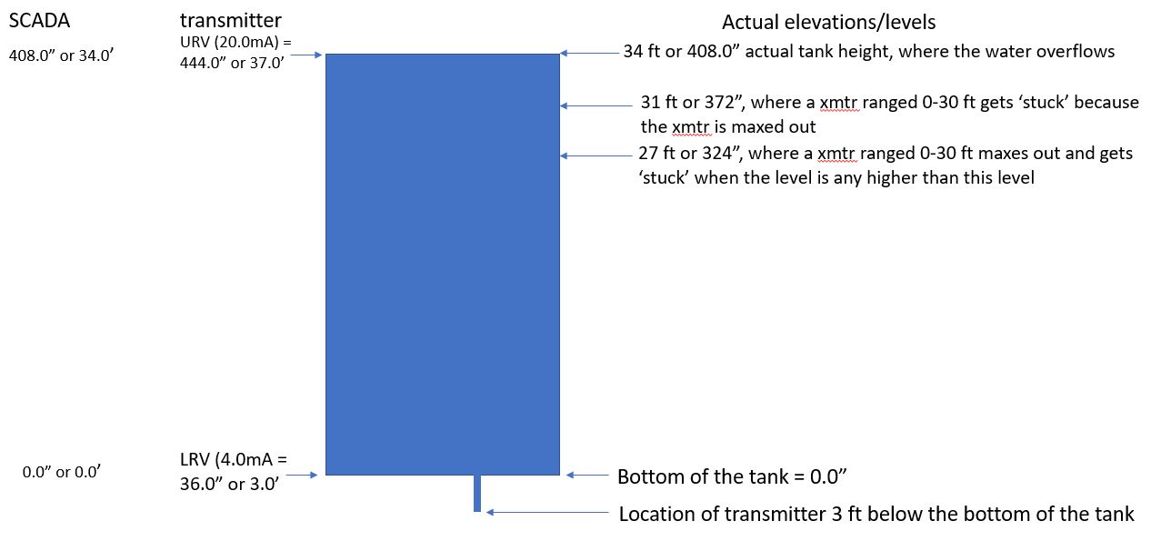
We put he scaling back and it seemed to be fine but the other day they had a tank overflow and while the readings are live and changing they are stuck around 27' which kind of matched the real level but when it overflowed it was still showing 25-27' so there was no high level alarm.

Today they let out enough water to drop the level by two feet and the historical trend makes it look like nothing happened. The historical trend for the last 8 hours still shows around 27’ or so the whole time. It actually seems to be slowly going up.

Any ideas on a setting in the transmitter that would cause this or did they get bad one?
 
Rosemount is a very high quality. I dont think they keep going bad like that. Are the fluid really dirty?
 
What was the previous style of reading, the second being pressure.. what was the first? Radar, ultrasonic, etc?


What are your scaling settings in the Rosemount for the analog style you are using? What is the functional range of the transmitter?


Is it scaling the full tank or a sight glass/Tube?

What does your PLC Scale the input to?

Does the HMI RESCALE It?

If a scale reads in inches via one method and you change to reading inches in another you have to make sure the entire path's scaling reflects the range changes accurately.

IF the transmitters top of the scale is 27' and that is lower than the tank's maximum you won't ready anything over 27 feet on the output. Its been told to max out there.

Make sure your scaling properly reflects real world capability. As well as your transmitter ... Had one that someone bought a couple years back on shelf as a spare. Our range we need to monitor is -25in WC to +25 wc. This one was capable of around -5000 to +5000.

The range we wanted was within its functional capability.. but not within its resolution capability. We wanted to monitor such a small amount if what it could do.. the 4-20 output didn't vary.

I suspect more the scaling is screwed somewhere.

Fun thing with liquid is.. pressure doesn't change from 1 cup or 1 million gallons. 1" below the surface or 1000' the pressure is the same at that level regardless of how much surface area you have.

PS... If someone is scaling it in the HMI... find them and slap them. I hate HMI scaling with a deep burning passion.
 
More information on the installation would be helpful. Are there remote diaphragm pressure seals on the transmitter? Is this a bubbler system? Is this potable water or waste water? A drawing would help determine the proper scaling for the transmitter.
 
The main thing that is bugging me is that the reading did not change much when the tank lost or gained a few feet and that takes about an hour a foot.

I don't have answers to all your questions but:

It's potable water.

I was told all three transmitters are the same make a model pressure transmitter. The original was setup to read pressure and give inches and the one on the shelf that they used for a month was just pressure. Then the new one was to be set up the same as the first giving a reading in inches.

Not sure why but in SCADA the Scaling Raw Full and Zero scale need to change from 6552-32760. Set by others for the transmitter that is giving inches.

Another issues is that the transmitter was reading 30' on its display but at the time the tank was at 27' and SCADA was also showing 27'. The transmitter is located about 3' below the tank and they may not have accounted for that in the new transmitters scaling but I don't think that explains why it's stuck around 27' even when the tank goes up or down a few feet. Not sure if that is a real issue as the new transmitter always seems to be at 25-27' but we can't just empty the tank to see what it shows at zero.

The tanks overflows at 34'.

They do not have the HART hardware/software but we did ask if they could get a configuration printout on the new transmitter from the vendor.

"Fun thing with liquid is.. pressure doesn't change from 1 cup or 1 million gallons. 1" below the surface or 1000' the pressure is the same at that level regardless of how much surface area you have."

Like inches of water column and what not. That messed with my head back in the day. Like a tank with a hose out the bottom, why don't all that water just just push out the end of the little hose when I rase the end up to the top of the tank? :)

I also hate do much of anything in SCADA that can be done in the PLC but get lots of requests for it. :(

I don't know much about transmitters but I thought you can adjust the sample rate, adjust the 4-20ma sent out and scale the readout on the display. Right now it looks like the ready maybe close but not moving correctly. Looking at the trend the value changes one or two feet and tenths of a foot when they say nothing is coming on or out of the tank.

Right now they just want to go back to the temporary transmitter that was reading pressure.
 
Last edited:
What is the brand of PLC? What make and model of analog input module is used on that PLC? What make and model of pressure instrument is used?

What does the scaling formula/instruction/whatever look like (screenshot is best here)? Or maybe the scaling is done in the instrument?

What level corresponds to the maximum raw counts from the input channel?


27' is 324", which is suspiciously close to one hundredth of 32,767.
 
1. >potable water

There is no need to compensate for specific gravity because it's water. The transmitter should be configured to read out in inches or feet of water column, not PSI, because you're measuring level in inches. Stay in the same units people use to refer to level. Pressure units can be converted level but that's how you run into these types of screw-ups. Why bother when everyone involved uses inches or feet for level?

2. Reason for stuck readings and overflow

> The tanks overflows at 34'.

>Another issues is that the transmitter was reading 30' on its display but at the time the tank was at 27' and SCADA was also showing 27'. The transmitter is located about 3' below the tank

>when it overflowed it was still showing 25-27'
>they let out enough water to drop the level by two feet and the historical trend makes it look like nothing happened.
>real issue as the new transmitter always seems to be at 25-27'

Numbers have meaning. There has been no drawing provided of what exactly you have and therefore the transmitter and SCADA configurations have been done on the fly with predictable bad results that do not reflect reality.

Here's what I deduce from the statements provided:

water-tank-level-stuck-at-27-feet-2.jpg


The transmitter is probably ranged 0-30 feet (or 360 inches). As such, it will incorrectly read 3 ft or 36 inches when the tank is empty (should read 0.0 level) because that's the remaining water column as shown by the 3 foot pipe beneath the bottom of the tank. ALL reported level values will be off by 3 feet if the elevation at the bottom is not taken into account.

A transmitter ranged 0-30 ft or 0-360 inches will max out at 30 ft or 360 inches even when the actual level is higher than 27 feet because the configuration of the transmitter or the SCADA is limited to a range lower than the tank's maximum. That's why the reading get stuck at 27 feet. Either the transmitter LRV or the SCADA is adjusting for the 3 ft elevation difference at zero level, but the level measurement is maxing out.

A transmitter ranged 0-30 ft or 0-360 inches will be incorrect by 3 ft or 36 inches at all levels because the elevation below the bottom of the tank has not been taken into account and removed from the reported output value of the transmitter (by adjusting the LRV value).

The LRV, the Lower Range Value, (4.0mA) is the reported zero level and the LRV should be configured for should 36 inches or 3.0 feet, to put the empty tank level at the bottom of the tank (or if not 3.0 feet, whatever the exact elevation difference is between the bottom of the tank and the center of the pressure sensor's diaphragm.)

The URV or Upper Range Value (20.0mA) should be 37.0 feet or 444.0 inches because the water can in fact get that high as you've discovered.

In summary, the transmitter should be ranged 36.0 to 444.0 inches water or 3.0 to 37.0 feet water to measure the entire water column from the connection point below the bottom of the tank to the overflow point.

The SCADA setting should be 0.0 to 34.0 feet (or 0.0 to 408.0") (actual tank heights) because 4.0mA represents the level at the bottom of the tank with an LRV of 3.0 ft or 36.0 inches and the 20.0mA value represents the level at 34.0 feet/408" (a measured 37.0 ft minus the 3.0 ft LRV value, or 444.0" minus 36.0" LRV).

If your site can't deal with measuring water up to the overflow point and insists on some maximum lower level, the transmitter settings for the representative 4-20mA range still have to match the SCADA interpretation of the 4-20mA range.
 
...but the other day they had a tank overflow and while the readings are live and changing they are stuck around 27' which kind of matched the real level but when it overflowed it was still showing 25-27' so there was no high level alarm....

This is odd: if the level was above the upper range configured for the 20mA output, would one expect them to be "live and changing?"

We don't know much about this process (i.e. it's typical thread), but there may two simultaneous outputs from a Rosemount: one from 4-20mA representing some process-defined configured analog range (e.g. 0-360INH20, or 36-44INH20 i.e. 3-37FTH20), and one transmitted via Hart protocol, which would output values outside the configured analog range. From a Rosemount manual:

  • Regardless of the range points, the Rosemount 3051 measures and reports all readings within the digital limits of the sensor. For example, if you set the 4 and 20 mA points to 0 and 10 inH2O[, respectively], and the transmitter detects a pressure of 25 inH2O, it digitally outputs the 25 inH2O reading and a 250 percent of range reading.
Of course, in the transmitter only the Hart protocol value can be scaled to specific units; the 4-20mA analog signal will always be an analog mA signal. Some PLC analog input cards can be configured to scale to engineering units on the fly, so the first value the PLC sees from the analog input card may be raw counts, e.g. 0 and 4095 for 4mA and 20mA, or it may be INH20. Again, OP has not provided enough information to provide any help here.
 
You should be able to set a negative LRV. Or an Offset value to account for the transducer being below tank level.

Check for those functional abilities. If you can set it to -3 for the LRV and 30 for the URV. then your 0' and 27' should read accurately. with a 3ft band on either side. You can then alarm at 27.5ft and have plenty of reaction time if it takes an hour to go up a foot.

Sample rate? I think you might more be looking for Dampening. Sample rate is how often it looks at the sensors own reading. Dampening is how long it averages a change over. Its a filter to nullify a wave. 5 second dampening will keep waves from showing up


Side Note:

I ran across a nice inexpensive HART programming package. ProComSol.. its about 900 bucks for the software, 400 for a Bluetooth modem. the software can be shared but only a single user can use it at once time. But its a licensed borrowing setup similar to what we're used to with Rockwell, check out, use, check in. Next guy can us it moments later on the other side of the country.

It works quite nicely. The only caveat is bench testing/configuring you have to rig up a 250ohm resistor as the BT modems generally don't have them.
 
Pactware is the freeware app for instrument configuration via HART.

The software is free, but one needs a USB/HART modem for physical connection to the device.


Pactware uses device specific DTM files, which need to be supplied by the device manufacturer. Not every HART device has a DTM, but the common devices do. A DTM file is not the same as a HART DD file. Many devices have both a DTM file and a DD file, each file used the appropriate app platform.


There's a Youtube video showing a guy installing the HART DTM files, but the Rosemount DTM's are already installed.


https://www.youtube.com/watch?v=DRSR5WOjX8U


USB HART modems range from $100 to $500.
 
Thanks for all the info and again, sorry I don't have more info.

drbitboy - It's a SCADAPack. We are getting a 4-20mA signal from the transmitter but they have not been able to give us the configuration yet.

danw - Lots of info there thanks. They may need an offset applied in the transmitter for the physical elevation of the transmitter but I think there is something else also going on. How did you insert the pic?

This is odd: if the level was above the upper range configured for the 20mA output, would one expect them to be "live and changing?"...

It is odd, the value was changing by as much a foot while they said nothing was coming or going out of the tank but it also was not clipped or ever flatlined.

They reset the transmitter and it showed a higher (Max?) reading of 34’ for second and then 30’ for 5 minutes and then settled back down to 27’ after an hour or so.

bwtMiUXggaYwmSN67

https://photos.app.goo.gl/bwtMiUXggaYwmSN67

They ended up putting the temporary PSI based transmitter back in then after changing the scaling from 0-36 to 0-693 it looked to be showing a good level for the tank. They then let enough water out for the level to drop by a foot or two and the SCADA value moved to match was showing the correct level.

When they did the same thing with the new transmitter the historical trend made it look like nothing happened. The historical trend for the last 8 hours showed around 27’ or so the whole time. It actually seemed to be slowly going up at the time.

4nVmC5evAQjw8o5K9

https://photos.app.goo.gl/4nVmC5evAQjw8o5K9
 
Last edited:

Similar Topics

Hi , Where i can find Mitsubishi PLC Card end of line & replacement model details. i am looking for Q02CPU replacement model. Please advice. thanks
Replies
2
Views
126
Hi , I am trying to replace an old inverter with a new one and its giving me issues . Once the new one was installed , the S7-300 PLC started...
Replies
3
Views
122
Hi Everyone, I replaced encoder 842D-60131331BXA with a new same part number. Dip switches and Preset Push button are considered. When I tested...
Replies
4
Views
225
Hello, I am kinda new to automation, I had an issue with 1743-EPAC which supply's 13 IO , when we inspected it there was a short circuit...
Replies
2
Views
143
A project recently went through to replace an old computer that was running Wonderware with a new computer. After a bit of work I was able to get...
Replies
7
Views
448
Back
Top Bottom