PLC under-reading water level by 20mm...

Mas01

Member
Join Date
Oct 2020
Location
Leicester, England
Posts
1,105
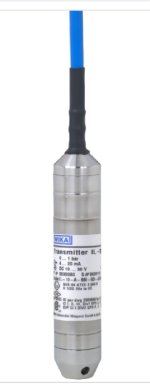
We've got a submersible water level sensor in our tank. We drained it, but when there was still a bit of water in the tank (about 20mm measured with a ruler), the PLC was reading zero, as though the tank were completely empty. I contacted the sensor supplier who told me that the sensing head (diaphragm) was about 20mm from the bottom of the sensor and that until the diaphragm was submerged, no water depth would be detected.
Maybe I'm thinking too simplistically, but to make this correction in the PLC, I was thinking of just adding 20mm to my calculated (mm) value. Is that okay to do?
Screenshot_20220420_083533.jpg
 
Last edited:
You can do that, but you have a blind zone where you dont know if you have 0 mm or 19 mm of water.

Instead of installing the sensor in the tank itself, have a tube parallel to the actual tank, and let the tube extend to below the lowest point of the tank. The top and bottom of the tube must be connected to the tank. Install the sensor in the tube and adjust its depth so the diaphragm is level with the bottom of the tank. If the tube is a transparent material, you also have a visual gauge of the tank level.

A more simple solution is to lower the sensor to just above the bottom of the tank. The sensor is measuring pressure so it shouldnt be affected by proximity of the tank vessel itself.
 
They are correct, it depends on the sensor & where it is located this is often the case, even diaphragm types that sit flush with the tank will often not see the very bottom of the tank most tanks will have a slightly dished bottom or slope towards the drain outlet, there is also a possibility the "ZERO" of the signal i.e. 4-20ma will not be 4ma unless scaled to compensate, however, it seems in your case that the offset is because the actual diaphragm is not directly at the bottom. Why are you worrying about it ? does it make a difference, remember by putting an offset of "20mm" will mean that even when the tank is completely empty you will then have 20mm showing on the level which is worse ?.
I suggest you leave it, at least this allows for some liquid to be present to wet the pump (running a dry pump even for a short time could do some damage to the seals).
You are not measuring the volume for any type of usage like customs or batching.
 
Thanks for the replies, much appreciated.
The water level is used for switching a pump on/off. 20mm depth is not a significant level for pump control, but I think a pragmatic solution would be to simply adjust the pump on/off setpoints by reducing them by 20mm (i.e. to account for the fact that actual depth is 20mm higher than PLC-calculated value).
 
I suggest you do not use 0 as the level control for pump off, perhaps 5mm or what ever, any drift of the sensor may mean if you switch the pump off at 0mm even though the level may be at less than the 20mm so the sensor should read zero, any drift in sensor or A-D conversion could mean it reading 1mm or more, so keeping the pump running, as you have 4 digital level sensors as well (I believe) arrange for the lower one to be below the 20mm level if possible & use this as a belt & braces sensor so as to switch off the pump should the level sensor give a false reading.
 
My first thought is "Does it matter?"

You don't give the total depth of the tank, but if it's 20 mm out of 3 m it probably doesn't matter. If it is 20 mm out of 50 mm, however ...

Second, and most importantly, does it affect the process? I would guess not. Is the 20 mm difference going to change performance? Quite often the on/off settings are fairly arbitrary anyway. If it ain't broke, don't fix it.

I'm not saying we shouldn't try for accuracy. I'm saying that it may not be worth much time and money to fix a problem whose only implications are theoretical niceties.
 
The water levels for turning the pump on/off does matter.
The ON level is 800mm, the OFF level is 250mm. i.e. nowhere near empty, but the aforementioned levels are important and need to be accurate for controlling the overall process. Hence, the 20mm difference needs to be taken into account.
 
Last edited:
I would offer this was by design for that process. Signal to the PLC zero level when the level is too low for the pump to run as most likely had design way of interlock to protect the pump.
 
The water levels for turning the pump on/off does matter.
The ON level is 800mm, the OFF level is 250mm. i.e. nowhere near empty, but the aforementioned levels are important and need to be accurate for controlling the overall process. Hence, the 20mm difference needs to be taken into account.


if the pump needs to come on and go off at those absolute 800mm and 250mm levels from the bottom of the tank, then the measured value should be converted to the actual level by adding 20mm to the current conversion, and leave the trigger level values alone. But also consider what @Tom Jenkins said, and if it is only the difference between the 800mm and 250m levels that needs to be accurate, then move on.

Changing the ON and OFF triggers by 20mm risks confusion, no matter how you document things.

Also, per @parky's comments, I would add an alarm when the converted level, with the 20mm added in, is below 25mm, to alert the operator that the value is suspect.
 
Sounds like you're assuming that the level measurements are inaccurate simply because of the elevated zero. I wouldn't assume that. I would test to see whether the reported level is actually off by 20 mm when the tank is not empty. If it is, then go ahead and add the 20 mm if you so desire, although this means that you'll never see the tank level at 0 -- even when the tank is actually empty.
 
You could add 20 mm to the reading as long as the signal is greater than zero or greater than the lowest accurate reading from the transmitter. Below the lowest accurate reading change the background color of the HMI object that displays the level, to indicate that the number is not to be trusted. And don't allow the unreliable numbers to be used for control
 
Let's get a few things sorted, first why is the water level for switching on/off the pump need to be that accurate.
Is the water chilled in process or in the tank or is it at ambient, I assume that the water is returned to the tank, the loss is minor i.e. due to evaporation etc.
If it is important perhaps just offset it by the 20mm but rely on the low level probe to absolute stop the pump, or adjust your 4 level controls so that high high level is whatever i.e. 1000mm, high level at 800mm & the low level 250mm & the low low level as low as you can get it so that even though you have an offset the pump will run between the two high & low level probes.
For those who are replying to this post, apparently there is also a 4 level switch system from what I gather from previous posts.
 
For clarification, this is a different tank to the tank I have mentioned in various previous threads (although it's part of the same water system) - sorry for any confusion. The tank in question in this thread has no float switches. Pump control is based solely on water levels as mentioned above.
Without going into too much detail, the water in this tank is situated in a near vacuum and the pump must turn ON at 800mm because there is some rotating equipment above this water level which must not get submerged (even partly) as that would invalidate the test. As for water temperature, it will get warm - as it's in a vacuum, there's no way for the heat to dissipate. The warm water will get cooled down as it circulates.
 
Last edited:
Sounds like feedwater for a liquid ring vacuum pump, but it doesn't really matter.

I'd simply add 20 mm to the depth reading and move on. If the "off" setting is 250 mm then you shouldn't have to worry about a constant zero reading at that last 20 mm in the bottom of the tank. It will only happen when draining the tank for service or when you have abnormal operations for another reason.
 
I believe it's a cooling system perhaps a cooling jacket within a process, we had loads of them for heat sealing machines & other types of moulding systems.
Cannot see why the need for that sort of accuracy.
The fact is that if the tank is not cooled then even a small increase or decrease in temperature will alter the volume so I do not see the problem of 20mm in say a 1000 mm tank.
 

Similar Topics

I'm curious, is there any PLC programming software that runs under Linux? Most software, like RSLogix or Step 7 only runs on Windows, which means...
Replies
21
Views
19,369
Does anybody here think this is possible? -or- Perhaps another way to ask: Does anybody know of a verified proof of this, for a program of more...
Replies
19
Views
7,063
Has anyone got any ideas on how to use older PLC programmers under WinXP, specifically ProWorxNxt (v1.2) or ProWorxPlus, both of these ran fine...
Replies
7
Views
2,631
I have been looking arround for a PLC Programm that works under linux or WINE. Not even ioProject from opto22 works under linux. RsLogix...
Replies
14
Views
9,079
Hello We have installed several G.E. Fanuc 90 70 PLC Everything was ok but suddenly we can not communicate anymore with any PLC with the software...
Replies
0
Views
24
Back
Top Bottom