Counter function help

RogerBrunner

Member
Join Date
Feb 2017
Location
Florida
Posts
42
I have a program that has been functioning great and now would like to add an additional feature. Currently the program is based on timing, timing is next to impossible to control in this situation.
The current flaw, if I1 is active and I2 process goes active it overrides the I1 process. Ideally I would like I2 not to take over until I1 has cleared, however as soon as I1 clears it will go active within a few seconds and at this point I2 can run process.
This is where I think counters would be better vs timers. Run the I2 process for 3 counts at I1 and then reset.
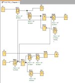
Process.JPG
 
can not you use I1 not state (B003) as an input to B001?
Then use B001 on state to block I1 from starting its cycle at B011 (this is already there, nevermind)
 
This appears to be Siemens Logo!; is that correct?

Does the image in the original post show how the system is coded without the new additional feature and had been functioning well, or does the image show the code after an attempt to add the new additional feature?

Which output, or outputs, should be controlled independently by I1 and and not affected by I2 going active while I1 is active, but should also be affected by I2 some time after I1 goes inactive? I.e. Q1, Q2, Q3 and/or Q4?

What is meant by "I1 process is active" and "I2 process goes active?" Does "process" mean "input," or does "process is/goes active" mean the state of some bit further downstream?
 
Last edited:
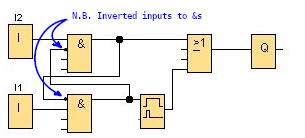
Without any response from OP, we cannae help with the specific case, but for the general case, here is one way have each input lockout the other:
Process_lockiout_00.png
The crossed and inverted inputs feeding back to the [&] instructions are the key takeaway.

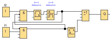
If there is a delaying action (e.g. debounce => On-delay timer) applied to one or both of the inputs, the approach is similar:
Process_lockiout_01.png
In this case, if the lower I1 input transitions from 0 to 1 after the upper I2 input, but also before the upper I2 input 0 to 1 debounce expires, then the lower I1 will interrupt and cancel the I2 debounce (On-delay timer) and lockout the debounced I2 from affecting the output until I1 transitions back to 0.

Again, I don't know if this is exactly what OP is looking for, but the basic approach should be generally applicable, even if the ancillary components are arranged differently.
 

Similar Topics

Hi there, I have been using ladder logic for quite some time on a variety of AB products. I've switched to function block for a lot of things...
Replies
7
Views
2,746
I have a Standard Panelview and Micrologix1200. Here is my problem, I would like to reset a counter (C5:5/DN) everytime I press F2 on the...
Replies
3
Views
4,115
I need to program a counter with an operator adjustable preset (to shut things off if the count doesn't reach the preset number between signals...
Replies
0
Views
2,999
if the timing value is set to 2, is it equivalent to 2 secs? is it the same with the counter function? the brand of plc is mitsubishi fx series
Replies
3
Views
6,161
Hi Guys, I have a 1769-L24-QBFCB1 that has the OK light flashing on the embedded counter module. The manual states it is a resettable fault, but...
Replies
0
Views
104
Back
Top Bottom