GX developer: I don't understand this pump starting logic...

There are some things that seem to be a little confusing first of all it is assumed this is the cooling recirculation pump is that correct ?.
If so, why wait until the level rises to the 800mm level to re-start the recirc?.
assumptions:
Providing the level is above min low level i.e. 240mm why not run the pump, why wait until it is above 800mm, surely providing there is a minimum level it is ok to run the cooling ?.
The filling of the tank could be auto or manual does not matter, the normal procedure would be to re-fill the tank either man or auto when the level gets close to the lower level not wait until below re-circulation level, this means the cooling recirc does not have to stop ?.
As I have said before, we had a number of systems like this that fed cooling water to sealing heads, originally, these were not supplied by the sealer machine suppliers, these were completely manual top up, often the heads would over heat & alarm on flow not detected, we automated the top up so that providing the level was above minimum the recirculation would run, when the level fell to something like 10% above minimum the top up would operate, there was a manual override, this worked in the same way as the logic posted.
I really do not see why you need to hold off the recirc until the tank is full.
If it was me, but the system actually or was desirable to also have manual run/stop during an auto run then this is what I would do.
Instead of having loads of operator interventions before production i.e. selecting & starting systems just have one auto start button, this would reset any manual selections & providing all the criteria have been met run the complete system in auto, any manual requirement should it be required could be selected & would stay in place until either a complete auto re-start or de-selected by the operator (this bit would depend on operational requirements).
all the filling/recirculation would be monitored & should a problem occur i.e. failed to fill within a certain time etc. would alarm to inform the operator & in the event that the problem was not rectified within certain times or parameters (safety of personnel or damage to equipment) halt the process.
Unfortunately, operators get used to the way it used to work & seem resistant to change, had this on a system, the company wanted more auto control on a batching system to alleviate the problems that occurred due to operator mistakes & sometimes their unwillingness to keep to production schedules, we modified the system but the operators complained, this was more to do with the operators believing they would be either reduced in numbers or made to do extra tasks. Ironically, a similar system we put into another plant some miles away where the "NEW" operators were sent to the other plant to learn the basics of the system asked why the existing system had so many operator interventions & why the operators were so resistant to a simpler & easier system to operate, the answer was "it is the way we have always done it".
 
Many thanks drbitboy & parky for the detailed help, really appreciated. Sometimes I feel out of my depth and other times I have half an idea on how to do something.
@parky, I think your suggestion of the manual mode button has already been implemented to control some cooling fans on our system...either auto control (fans on at 40c ) or manual control (turn them on/off whenever you like). So that might be useful to compare to your idea.
I'll have a look at both your suggestions tomorrow when I'm back at work. I'll be sure to report back with an update.
 
To answer some of your questions @parky...we have a closed container into which water is pumped. This pumped water enters a series of spray bars which spray water onto rotating blades. As the water strikes the blades, the blades become worn and fatigued - to fatigue the blades and cause them to wear out. This is the objective of the test. This water falls to the floor of the container and accumulates. The water must not go above 800mm otherwise components inside the container would get wet and damaged...the only components we want water to go onto is the blades. Hence the need to purge the water at 800mm. The lower limit where the pump is turned off is just to ensure that the pump doesn't run dry. It is basically a scavenge pump, which is switched on/off to purge the accumulating water.
 
Last edited:
...I'll be sure to report back with an update.

We look forward to it.

My focus providing a mental model of how a PLC operates (cf. here ;)), which is measuring and controlling the process over time; an alternative analogue for time in that model is sequence of events. Once we have that model, PLC programming boils down to bookkeeping of bits.

The first thing to understand is that digital PLCs have scan and I/O cycles, and many PLCs run them synchronously i.e. alternately: one I/O cycle of read inputs and write outputs, then one scan cycle of executing the program instructions based on the inputs and output and re-generating the outputs, then repeat (i.e. another I/O cycle, then scan cycle, etc.). I could go on, but @Ron Beaufort's PLC bootcamp videos are the best; if you have not seen them take two hours out of your day and watch them here.

The second thing to understand is that, in addition to inputs and outputs, the PLC has internal memory, with which it can maintain internal state between program scans, so previous state (or states) of a PLC are analogous to another set of inputs to the program scan i.e. the program logic can know what the state of the process was on the previous (in time) scan when it it re-running the program logic on this latter (in time) scan with a different set of inputs. That is really what the Seal-in, Start/Stop, and State/Fault circuit patterns are all about i.e. the current state of the I/O on the current scan and the previous state of the process from the previous scan (or scans).

For example, with the Start/Stop Circuit pattern for this thread, when the level is above 800 then of course that will turn on the pump, and when the level is below 240 then of course that will turn off the pump. But the real issue is when the level is above 240 but also below 800: without memory of the process state at the end of the previous (in time) scan, the code will not know whether the level just came down from 800+ and the pump should be told to run, or if the level just came up from 240- and the pump should be told to not run.

The vast majority of non-trivial (i.e. other than outputY = inputX) PLC logic boils down to a Start/Stop Circuit:
  • The Stop condition determines when the output must be 0
  • The Start condition determines when the output should transition to 1
    • Assuming the Stop condition is not True,
    • I.e. the logic is Stop-dominant
  • The Seal-in condition determines what to do when neither the Stop nor the Start condition is True, based on the time history of the process state.
As you mentioned in an earlier post, most of the start/stop logic you had seen used Set/Reset logic; all that means is that the Seal-in condition is built into the Set and Reset instructions' logic i.e. if a Set or Reset instruction is not fed by a True rung, then that Set or Reset instruction not only does not write a 1 or 0, respectively, to the output bit, it also does not change the state of its output bit.

Excuse me for waxing so lyrical about this, but I really think that if someone groks the Start/Stop Circuit pattern, and I mean more than just "This is Start, this is Seal-in, ...," but really understands that it is about time, then they will have a good handle on relay logic.


_
 
Ah.. It becomes clear, I presumed you were still talking about the cooling top up & re-circulation.
The update you posted would have helped if you had posted that there is nothing better than a description of the part of the process & how you wish to control it. May I make a suggestion, try to include the process & what you require (obviously without giving away secrets of the "secret process", well been in this game for a long time & I doubt there is very little out there that is so unique).
Actually, done a similar system but it was not on a test bed, it was where water was required and for a type of cleaning of parts & the sump was purged after a certain level, although the only manual control was for maintenance purposes.
 
Last edited:
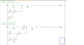
Here are two rungs of logic that should do what you want, the first rung is based on no Auto/Man selector in other words the auto still works regardless so if the level reaches > 800 then it latches in & runs the pump until it reaches the 240 level, if the manual stop button is pressed then providing the level is below 800 then it will stop, it can be re-started as long as the level is above 240mm.
The second rung is basically the same however, it introduces an Auto/Man selector so that in auto it just works in auto, in manual it just works when the start/stop buttons are pressed, however, should the level fall below the 240 level it will stop, if the level rises above the 240 it will enable the operator to re-start the pump it does not need to be above 800 to manually start.
You only need one of these rungs it depends on how you want to control it.

Pump control.png
 
Here are two rungs of logic that should do what you want, the first rung is based on no Auto/Man selector in other words the auto still works regardless so if the level reaches > 800 then it latches in & runs the pump until it reaches the 240 level, if the manual stop button is pressed then providing the level is below 800 then it will stop, it can be re-started as long as the level is above 240mm.
The second rung is basically the same however, it introduces an Auto/Man selector so that in auto it just works in auto, in manual it just works when the start/stop buttons are pressed, however, should the level fall below the 240 level it will stop, if the level rises above the 240 it will enable the operator to re-start the pump it does not need to be above 800 to manually start.
You only need one of these rungs it depends on how you want to control it.

Just to confirm: in the lower code, M3 is the man/auto toggle button (possibly a lamp on the HMI). M0 is the request to manually start the pump and M1 is the request to manually stop the pump, is that right?
 
M0 is the Start button M1 is the stop button & M2 is the auto/man button.
So it is the same as the top rung only the addition of the Auto/Man button.
You will have to allocate the bits for those i.e. any spare bits you have.
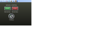
Note: the M2 (Auto/Man) is normally open so in auto (default) to switch to manual this would require a button that is toggled (select this type instead of momentary) this would stay "ON" while plc is in run but a power down the bit would reset on a power up default to auto. Note: on the Auto/Man button need to untick the OFF/ON at the right of the text field as shown in the pic.

Start_Stop.jpg
 
Just to confirm: in the lower code, M3 is the man/auto toggle button (possibly a lamp on the HMI). M0 is the request to manually start the pump and M1 is the request to manually stop the pump, is that right?

This is referring to the image in @parky's post #13, not @parky's latest post #21.

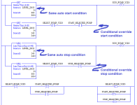
In post #13, M3 is a result bit set by the PLC, and not an input set via the HMI, that says "operator's manual override logic says the pump should be running now." It is a combination of


  • M1: bit set via HMI; value of 1 means HMI start button has been pressed, and the start directive may apply to any selected pump (or no pump, if none are selected)
  • M2: bit set via HMI; value of 1 means the HMI stop button has been pressed, and the stop directive may apply to any selected pump (or no pump)
  • M20: select the Y2D5 pump as the pump to which to apply any start (M1) or stop (M2) presses on the HMI
  • M3: bit set via PLC "operator manual override" logic
  • Operator Manual Override logic: the logic described by OP @Mas01 in post #10:
...Now the operator wants to have a manual override, so that they can switch the pump on/off at will, but only when the level is between 240 and 800mm. IE below 240mm or above 800mm , the operator is locked out & cannot manually operate the pump. ...
Please correct me if I am wrong, but as described by the OP @Mas01,

  • this process has no global "Auto/Manual" function or HMI button,
  • It has only
    • a Pump Start button,
    • a Pump Stop button, and
    • an unspecified number (at least 1?) of Pump Select buttons that tell the PLC to which pump any start or stop events should be applied.
  • The operator manual override logic should only have an effect when the level is between the low (240) and high (800) limits, so
    • When the level is above 800, the pump must run, no matter what the operator does with the Pump Select, Start, or Stop buttons.
    • When the level is below 240, the pump must not run, no matter what the operator does with the Pump Select, Start, or Stop buttons.
The second rung in @parky's post #21 is more or less identical to the second image in my post #12, with a few caveats:
  • the one functional difference is the behavior of one unlikely, nearly-impossible edge case
  • @parky did not include the HMI Pump Select bit, that directs the HMI start an stop bits, so
    • M0 is a combination of (HMI Pump Y2D5 Selected) and (HMI Pump Start), and
    • M1 is a combination of (HMI Pump Y2D5 Selected) and (HMI Pump Stop). and
    • M2 does not exist in this process as an Auto/Manual HMI switch, and should be removed from the logic shown
  • @parky did not show the PLC code that assigns 0 to the bits assigned 1 by the HMI (Set and Forget).
- drbitboy, DMD
_
 
Last edited:
Apologies, I was unable to do any code updates today because the rig was running all the time. I need some rig "down Time" to allow me to do the update... I've already made the mistake once of writing to the PLC while pumps were running (causing them to momentarily judder), not something I want to repeat again in a hurry. I will try tomorrow. Thanks chaps.
 
The last codes I posted are the ones (just thought you had a typo "M3" instead of M2), @DR: the buttons are new ones for manual control not the existing ones which I believe are for selecting them to start in Auto (unless the existing can be modified), the "START & STOP" buttons are NOT set on the HMI they are momentary i.e. on when pressed, the Auto/Manual one is a toggle i.e. press once it sets the bit press again it resets it, that is why I showed the GT designer screen as it is not obvious how the toggle works, although you select a radio button on the pop up (first tab) on the second tab you have to de-select the OFF=ON radio button. although I showed it as just a press button you could change it to an animated selector this requires a little more work but there is one in the in-built library. see pic.

Auto_Man.png
 
I still don't think @Mas01 is looking for an Auto/Manual mode; the system is always in Auto: the pump starts when level is above high limit; the pump stops when level is below low limit; see here:
below 240mm or above 800mm , the operator is locked out & cannot manually operate the pump.
What @Mas01 wants is a way, from the HMI by pressing a "Select Pump Y2D5" button, then a "Start selected pump" or "Stop selected pump" button, to allow the operator to override the current run state of pump Y2D5, but only when the level is between the limits.

So the original basic algorithm sans override could be re-written using Set/Reset like this:
sump_basic.png
@Mas01 indicated many of the other start/stop circuits were coded like that, so it should be easily understood: the Seal-in of the Start/Stop Circuit pattern has been replaced by the "do not change the output" policy/behavior of the Set and Reset instructions when their input rungs evaluate to False. Also, because the Reset (-(U)- Unlatch) rung is after the Set (-(L)- Latch) rung, this algorithm is Stop-dominant.

Adding the operator override would then look like the image below.

Note that the [GRT(>) LEVEL_D353 240] instruction on the bottom branch of the first rung is only there to make it easier to read the intent of the override logic, and that instruction can be removed, because the primary basic algorithm's logic is Stop-dominant: i.e. even if that instruction is removed and the operator puts a 1 in RUN_PUMP_D353 via the first rung when the level was at or below 240, the second rung would immediately overwrite a 0 into RUN_PUMP_D353 and ensure the pump does not start.
sump_with_override.png
 
That is why I did the top rung as one of the alternatives, this allowed to start/stop the pump manually without the need for an Auto/Man selector so gave him both options, it still works in auto so will stop when reaches low level but does not need to be at high level to start it manually, as for not being able to start the pump at high level is ridiculous as it would auto start anyway if not in manual. if it was above high level surely you would want to be able to start the pump to lower the level.
You are unlikely to get information about the whole process as it appears that either the original supplier or the company he works for are reluctant to divulge too much.
 

Similar Topics

Well, I've decided to start a new project, and like all projects, it has already gone horribly wrong. I purchased a PLC device (supposedly a...
Replies
2
Views
102
Does anybody have any samples of how to "Create and Use" UDT's in CCW Developer Edition? (I am using v22) I can't find any information from...
Replies
3
Views
298
I'm trying to manually convert a Beijer E200 HMI project onto to a new Mitsubishi GOT gs2107-wtbd. The PLC is a very old A-series AS1CPU and is...
Replies
1
Views
373
Hi One of the PLC's that I maintain/update is a Mitsubishi Q-Series, probably installed about 10 years ago. At the moment, ALL the wires from...
Replies
13
Views
1,156
Has anyone put together a combination of the Beijer iX Developer software and a Rexroth L54 controller over ethernet? Can't seem to get the...
Replies
2
Views
542
Back
Top Bottom