Electric Chair

Join Date
Oct 2012
Location
canada
Posts
4
another halloween plc project.

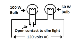
so i have 2 incadecent lights at the top of my electric chair. when the relay engages the NO of the relay goes through a dimmer switch to dim the lights and start the electric chair sounds. this is not very realalistic as it is Bright light Dim light. is there a way with my Omron CP1L plc with cx programmer to have the lights dim without the dimmer switch and maybe go from bright to gradually dim?
 
You could do it with Pulse Width Modulation (PWM), but you would need a Solid State Output (i.e. Triac, or Transistor) to switch fast enough for it to work. I haven't done anything with a CP1L, so I am not sure what it has available.

Stu....
 
I had a quick look at the CP1L, and it does have a couple of Pulse Outputs. Those might help you out, otherwise, you will have to roll your own. Do a search on here, and on Google, and you should find lots of examples.

Stu....
 
connect a fluro starter in serirs with the lights (1 per light)
that may look impressive
 
Pulse width modulation and power SSRs rated for the wattage of the lamp should work well.

I don't know about florescent lamp ballasts being a wise thing to wire it up to...???
 
Add an industrial electric bin vibrator on the under side of the chair to add a little extra tingle! An alternative is a large hand-held body massager. Screw the vibrator to the chair bottom with hidden metal straps or bands, and use your PLC to turn on the 120 volt vibrator power when your seat switch is triggered.

Your chair is wooden like all the old electric chairs, right? If you strapped a 120 volt vibrator to a metal chair, a short circuit could cause it to become a real electric chair.
 
Last edited:
Put all these outdoor circuits on some type of GFCI, for the safety of your customers and to avoid any liability damages.
 
Put all these outdoor circuits on some type of GFCI, for the safety of your customers and to avoid any liability damages.

Yeah, normally...

But isn't this supposed to be an "Electric chair"?

A GFCI would defeat the purpose... :)
 
connect a fluro starter in serirs with the lights (1 per light)
that may look impressive

I can only imagine!... LOL

Actually, it would look pretty neat:

http://www.youtube.com/watch?v=B4lbDIA0dZk&feature=related

Keep in mind for you kids at home that the rest of the fluoresent circuitry is needed to make this work, I don't imagine that the starter itself would last long hooked directly to 110V.

(Although I might try it at home, it's been too long since I blew anything up). :ROFLMAO:
 
Pulse width modulation and power SSRs rated for the wattage of the lamp should work well.

I don't know about florescent lamp ballasts being a wise thing to wire it up to...???
not the ballast the starter
it is a normally closed switch that opens to fire the ballast.
this is an old fake campfire trick - it makes the lamp flicker on and off odd times
 
But isn't this supposed to be an "Electric chair"?
:nodi: Yes, but in case it really works, you need the GFCI to protect your rear from the vulture lawyers.

...this is an old fake campfire trick - it makes the lamp flicker on and off odd times
Ian, to create the campfire trick, do you use the starter with the normal preheat type of ballast, or how is it different from normal to create the flicker? (Our voltage here for lighting normally is only 120 volts, so the ballast also has to be an auto-transformer as well as a current-limiting device.)
 
Last edited:
not the ballast the starter
it is a normally closed switch that opens to fire the ballast.
this is an old fake campfire trick - it makes the lamp flicker on and off odd times

Neat! Now I will have to try it. :)
 
@ lancie1
the ballast is a choke that 'Fires' the Fluro
you need to look at the CCT
there are two filaments a ballast (Non-Electronic) and the starter.
the active goes to the ballast then one side of one fillament the starter is in series with the other side of that one and one side of the other fillament - it inturn goes to the Neutral.
Esentually the Fluro starts with a HIGH voltage Back EMF jolt as the Starter disconnects the load.
that is why you can remove a starter after the Fluro has started.
- The voltage, being 120 V is no different. at the end of the day it dont use the starter after the light is on.
 

Similar Topics

Rs485 module then 2 wire belden 9841, modbus network picking up electric meters. Does this need to be wired as a ring or a radial? Thankyou
Replies
1
Views
78
Hello PLCS.Net Forum, First time posting. Let's assume I am a novice. BASIC PROBLEM: My servo/linear piston is no longer zeroed to the...
Replies
9
Views
194
I have an old PLC (circa 2007) consisting of Telemecanique/Modicon/Schneider Electric devices. The system has developed errors and unfortunately...
Replies
2
Views
209
Hi Friends, I am facing a problem with encoder adjustment in Sew Electric Cylinder CMS71L. encoder using is Sick Hiperface Drive is MOVIDRIVE...
Replies
17
Views
762
Hi, I am stuck with these SE cartridges, I am trying to add a second serial port rs485 to a M221 PLC. What is the difference between TMC2CONV01...
Replies
1
Views
109
Back
Top Bottom