PLC5 Physical Analog Input

tjoneill

Member
Join Date
Jul 2007
Location
Michigan
Posts
66
Hi again all.
I have a slight problem. I have a PLC5 analog card that has a bad 4-20 input that has to be moved to another but cant find the actual address (any of the actual 4-20ma addresses)
I had an old D-TAM HMI controling the prossesor with BTW instructions in the program that was replaced with a PV 1000. Could these Analog Addresses be in the setup screens in the BTW instructions?
Thank you in advance
Tim
 
If the address is being controlled by block transfer then it may not be directly listed in the program.

If it is a block transfer then somewhere the analog channel data has to be copied to the M:0 or M:1 buffer.

I try to map all the block transfered addresses into the ladder even if only using dummy rungs so you can see the status of the data being transfered more easily.
 
Greetings Tim ...

first of all, the (well-intentioned) information that you've been given above relates to the SLC-500 family of processors ... it is NOT correct for the larger (and more complicated) PLC-5 system that you're working on – so don't let it confuse you ... key point: all Allen-Bradley systems are NOT the same ...

attaching your program was a GOOD idea ... unfortunately the I/O Configuration table hasn't been filled out – so the documentation is sort of sketchy ...

based on what I can tell, you have TWO analog input modules and each of these APPEARS to be an 1771-IFE ...

I've done my best to extract the information that you need based on several ASSUMPTIONS ... if you have any additional questions, feel free to call me up (even this weekend is ok) and I'll try to help you through this ... note that I will be offline until sometime tomorrow – so if you post anything here (or if you send me an email) I won't get the message today ...

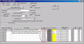
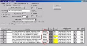
I've attached two pictures below – one for each analog input module ...

see if the addresses that I've circled in red help you out ... notice that each (ASSUMED) 1771-IFE analog input card has 8 channels available ... the address descriptions (the existing documentation) seem to make sense – but naturally I can't be sure without knowing exactly how your system is actually (physically) put together ...

finally, you should already know that the 1771-IFE modules contain JUMPERS which select whether each channel is wired for voltage or wired for current ... if you're moving a field input from one channel to another, it would be a good idea to open the module and make sure that the jumpers for the "new" channel are correctly arranged to match the input signal ...

if you need more help, it would be a good idea to confirm exactly what type of analog input modules you're using (full catalog numbers please) – and also how those modules are arranged in your chassis ... knowing the actual size of the chassis would be helpful too ... I've ASSUMED that you're using a sixteen-slot local (processor resident) chassis ... suppose that we LETTER each of the slots "A" through "Q" to remove any "one-slot" – "two-slot" – "half-slot" addressing ambiguity ... yes, that's a total of SEVENTEEN slots – not sixteen ... in a PLC-5 system the "extra" (uncounted) slot is for the processor ... (the label on the chassis "lies") ... so ... if you consider the processor to be located in slot "A" then the two modules that I THINK you have for your analog inputs APPEAR to be located in the slots lettered "O" and "P" ... if your hardware is different, then you might want to nail down how it's actually physically arranged before you go much further ...

one more note: your "local" chassis (the one with the processor in it) is using the "one-slot" addressing mode ... IF (that's a big IF) you actually are using another ("remote") chassis too, then there's no guarantee that it is also using "one-slot" mode ... so – IF there's another chassis involved, it would be a good idea to check the DIP switches located on that chassis' backplane ... note that the "slot" addressing mode for a remote chassis can NOT be conclusively determined from the program file ...

hope this helps ... good luck with your project ...
01_5_0.jpg 01_6_0.jpg
 
Last edited:
What address went bad? It looks like both of your input cards are Differential. Is that correct? If the above is correct you should have N10:257~261 open. I just ASSuMEd you are using IFE card in the R1,G5,and G6 is that if that is correct

Ron is much faster than I am I was typing. He is always 2 steps ahead
 
Thanks Ron and Jeff
I am very new at the PLC5 family and cant find the configuration screen for the Analog cards that is shown in the pictures. Looks to me that I have too bad channel n10:57 and move to an open channel but having a very hard time finding where to go.
Thanks
Tim
 
cant find the configuration screen for the Analog cards that is shown in the pictures.

the reason that you can't find them is that the I/O Configuration table hasn't been set up ... once you've confirmed the actual catalog numbers and locations of the modules involved, we'll be glad to help you set up the I/O Configuration ... after that, a few clicks of the mouse will open up the screens that you need ...

PLEASE NOTE that the screen shots I've posted are PROBABLY correct - but again, I can't guarantee that they are until I know exactly how your hardware is put together ...

SIDE NOTE: for any SLC-type people who might be confused by all of this ... many SLC systems are capable of automatically "reading the I/O" and then automatically configuring the table for you ... the older and more complicated PLC-5 systems can't do this ... specifically, you (the programmer) must tell the software what type of modules you have installed - and how you have them set up - before you (the programmer) can ACCURATELY fill out the I/O Configuration table yourself ... the main problem here is that we don't know (for sure) exactly how Tim's system is set up - and the RSLogix5 software can't help us out in this case ...
 
Last edited:
Ron,
Thank you very much for spending some time to help me out.
Anyways,here is the rack config. you need.
SLOT 0-plc 5/25 cat.#96736B71
SLOT 1 AC INPUT CAT#1771 IAD
SLOT 2 AC INPUT CAT#1771-IAD
SLOT 3 OUTPUT CAT#1771-OW16B
SLOT 4 OUTPUT CAT#1771-OAD
SLOT 5 OUTPUT CAT#1771-OAD
SLOT 5-11 OPEN
SLOT 12 10-30VDC INPUT CAT# 1771-IBD
SLOT 13,14 ANALOG CAT# 1771-IFE A
SLOT15 ANALOG OUT CAT#1771-OFE2
 
please check your Private Messages ... my "typing" time is all used up for today - but I do have some "talking" time still available ...
 
We got it!
Thanks for the help. A special thanks to Ron for taking the time to troubleshoot my problem on a sunday afternoon.
Tim
 

Similar Topics

I am using the following formula and I am getting error, Invalid Expression - too many closing parenthesis. when i copy the formula to notepad or...
Replies
4
Views
141
Preface: Kinda long, so I made section titles Intro: I just want to see if anyone here has seen anything similar. A PLC5-40 series C enhanced...
Replies
3
Views
360
Hi, can anyone help me get a pdf file for this RSP files. They are from a PLC5. Thanks
Replies
5
Views
506
Hello all, I am seeing this behaviour where an integer file (N46:33), has an integer in binary (11110) which is 30 in decimal. I did a...
Replies
7
Views
510
Back
Top Bottom