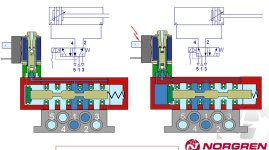
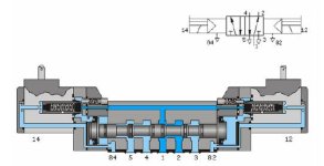
Safety question. How does a 5/3-way pneu valve behave when air is off ?

JesperMP

Lifetime Supporting Member + Moderator
Join Date
Feb 2003
Location
ᚴᚬᛒᛅᚾᚼᚬᚠᚾ
Posts
16,303
Hi there.

I have a quite common pneumatic installation, with a pneumatic cylinder that activates a diverter plough by lifting and lowering.

There is a padlockable isolator/dearation switch in front of the solnoid valve block that controls the cylinder.
The solenoid block is the 5/3-way type with deareation in the middle position (see attached diagram). The air is supplied from the isolator switch to port 1 in the diagram.

I am wondering what happens in case the solenoid is active, and the isolator switch is closed (incoming air is deareated).
Does the solenoid go into the middle postion, because it looses the piloting air ?
Or does it stay in the current position ?
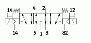
5-3-way_mid_exhausted.GIF
 
Hi
According to your attached diagram , It will not move back even if the inlet air is depressurised or deaired.
 
I would have thought that due to the spool being sprung return the valve should go to the middle position.
So the inlet port would be blanked but the other 2 ports would be straight thru, usually venting to atmosphere.
 
So far, 2 votes for that the valve stays in the active position, and 2 votes that it will go back to the middle position.
I guess I shall have to do some tests, only I have to find a suitable test object. Hm..

In case you are wondering, then I need to know if the safety switch in front of the solenoid block is enough to remove the energy from the system. If it is not, then I have to come up with a much more complex system.
 
My vote: The Valve stays in the active position. It only returns to the center pos. if it looses power.
 
A pilot operated valve will return to center position IF it has spring returns.

If it does not have spring returns, then it will remain in the last position.

You original diagram shows spring returns. (the "z" shaped lines on the ends) So that valve will return to center when AIR is removed even if POWER is still applied.

The power only controls the opening of air passages for the pilot air to move the spool.

*IMPORTANT* Since this is safety related, please give me the model/Part# and I can give you a 100% confident answer.

Unless you are 100% positive that the drawing you attached goes to the valve you are going to use. If that is the case, then the answer above is official. (although I am still curious about the actual #)
 
If the main spool is pilot operated, and the pilot exhaust is not restricted, removing the pilot air should allow the main spool to return to center. It may take a short period of time for this to occur, depending on whether the pilot exhaust is muffled, whether it vents through the main valve exhaust or externally, and, if vented to the main exhaust, it will depend on how much air is being released through the vented disconnect valve.

I would expect the valve to return to center within a very few seconds in most situation.

The pilot poppet will still be held open by the solenoid coil, but no pressure should exist in those passages to move the main spool. When the supply air valve is again opened, the spool would immediately shift once the pilot pressure reaches its minimum operating pressure. This may not be the safest situation, and should be considered.

Some machines are set up with a main air pressure switch as part of the safety circuit, so that if a hose ruptures or the main supply is turned off, the e-stop circuit will drop out, and that would kill all power to the affected solenoids, and everything else that needs to have a certain air pressure in order to function safely.

My bet is on return to center, unless the pilot air is trapped or fed from another air supply.
 
Last edited:
The springs at 14 and 12 are only for the manual operation of the valve.
The main valve does not have return springs.

attachment.php


So, by removing the pressure at "1", the valve will keep its position.
Tomorrow I will be at a machine that has a valve like this and, to be shure, I will do a test.
 
It *is* or *will be* spring return, as shown in the diagram.
And there seems to be separate pilot air relief for the valve in the diagram (it also looks like the is a small typo, the air relief port # 14 should probably be # 84).

I was also thinking that maybe it will take some time for the pilot air to be relieved, and thus the valve to return to the middle position. I think that up to 1-2 seconds is no problem. 10 seconds and up would be a catastrophe. That would mean that the maint would shut off the air, hear the air being relieved, start work on the device, and THEN the valve switches to the middle postion starting a movement. No, 1-2 seconds is max.

As to the exact type #, then the shown diagram is one I quickly found on Festo's website.
However, I would put it the other way around, if it works so that all air is relieved within 1 second, then that is what we want and we will *get* the proper valve from whatever manufacturer or size that will be used in the end. It is the principle I want to be somewhat certain of.
 
Does the solenoid go into the middle postion, because it looses the piloting air ?
Or does it stay in the current position ?

If it is like your drawing, then ivo.maenen is correct it looses pilot air.

If it is like my pic it's direct acting, solenoid acts directly on the valve spool (Numatics brand).

direct acting.jpg
 
So far, 2 votes for that the valve stays in the active position, and 2 votes that it will go back to the middle position.
I guess I shall have to do some tests, only I have to find a suitable test object. Hm..

In case you are wondering, then I need to know if the safety switch in front of the solenoid block is enough to remove the energy from the system. If it is not, then I have to come up with a much more complex system.

Jesper
The US Navy lost a newly built submarine in sea trials Thresher SSN 593. What we heard was that in addition to flooding from which they recovered and got to scope depth she went down because of failure of HP blow valves. This was interesting to us since we served on a sister ship SSN 596.

I think you hit it on the head by saying the only way for you to know is to run a test. I would advocate simulating on a bench to get a really good idea of what this valve is going to do for you under the operating criteria you define.

Granted you probably will not sink the factory
but the money spent on testing
will prevent that sinking feeling you will have if valve does not perform how you want.

Dan Bentler
 
Gates '14' and '82' could also be '14' (internal connection between gate 1 and 4) and '12' (internal connection between gate 1 and 2).

Then they are used as a part of the function of Y1 and Y2. '12' and '14' will than give the right piloting-pressure to move the actual 5/3-valve.

This is done if the pressure for '12' and '14' is different then the pressure used for '1'. Look at it like this: '1' = 3x400V, '12'-'14' = 24V. Then '1' can also be vacuum.
 

Similar Topics

Hi I have a yaskawa gp7 robot arm which I am going to use for machine tending with a cnc mill. Is it a good idea to buy a SICK laser scanner for...
Replies
5
Views
232
Hey guys, the scenario is: I have already completed the drawing package for my system utilizing an A-B 440R-N23126 (Minotaur) safety relay. SoS...
Replies
0
Views
134
I've ready through the the previous posts, and we've worked with safety design for a long time. In the past, we worked with Pilz directly, and...
Replies
9
Views
559
So first off I know everyone hates directly answering safety questions and I want to start by I will take no ones opinion as rule but looking for...
Replies
12
Views
1,362
Hi all, I'm working on a safety circuit and had some question about fusing. Incoming supply - 120V/15A Power supply - PSL-24-060...
Replies
5
Views
579
Back
Top Bottom