OT: looking for a HV out signal conditioner or ring tach

strantor

Member
Join Date
Sep 2010
Location
katy tx
Posts
401
I'm retrofitting a cabling machine from 25HP DC motor & drive to 25HP AC motor & drive. The machine currently utilizes the DC tach's 50V/1000RPM signal for purposes other than the DC drive's speed feedback. So the new AC setup needs to incorporate the tach, but the non-business end of the motor is covered by the encoder assembly. I have not been able to find a low-profile pancake-style hollow shaft DC tach for the business end, so I had another idea. I can use a Frequency>voltage converter to turn the tach signal into an analog voltage signal. The problem is that I can't find a converter with a 0-150V output (corresponding to 0-3000RPM). I can find plenty with 0-10V output but that's too low. If I could find an additional signal conditioner for 0-10V > 0-150V, I could make that work (F/V converter > signal conditioner) but I can't find that either.

Any ideas?
Thanks
 
Just wondering??
What if you used a small DC drive 0-10vdc input 0-180vdc output??o_O
 
Now there's thinking outside the box ;) . I bet would work if the drive had a true linear analog voltage output, but I have a suspicion that anything available on the market these days is going to have a fixed 180v output with 0-100% duty cycle PWM. I would love to be proven wrong though. I will look and see what I can see in the way of dc drives.

...or maybe that PWM could be smoothed out with a RC circuit. Maybe...
 
I'm retrofitting a cabling machine from 25HP DC motor & drive to 25HP AC motor & drive. The machine currently utilizes the DC tach's 50V/1000RPM signal for purposes other than the DC drive's speed feedback. So the new AC setup needs to incorporate the tach, but the non-business end of the motor is covered by the encoder assembly. I have not been able to find a low-profile pancake-style hollow shaft DC tach for the business end, so I had another idea. I can use a Frequency>voltage converter to turn the tach signal into an analog voltage signal. The problem is that I can't find a converter with a 0-150V output (corresponding to 0-3000RPM). I can find plenty with 0-10V output but that's too low. If I could find an additional signal conditioner for 0-10V > 0-150V, I could make that work (F/V converter > signal conditioner) but I can't find that either.

Any ideas?
Thanks

0-3000 RPM -> 0-150 VDC equals to 50mV/RPM

take a look at GTB9 (http://www.baumerhuebner.com/analog-tachos.html?&L=1
 

Thanks. I just had a read through the manual for that drive and didn't see anything about PWM, but I also didn't see anything about analog voltage regulation. I'm going to send an email to KB and ask.

0-3000 RPM -> 0-150 VDC equals to 50mV/RPM

take a look at GTB9 (http://www.baumerhuebner.com/analog-tachos.html?&L=1

From what I can make out in the Install guide, This appears to be another non-business end shaft-end tach. I need a pancake type that fits on the main end between the motor and the pulley. Huebner does make dual tach/encoder assemblies which is what I might end up having to use.

EDIT: Also, the motor is not IEC frame size, it is NEMA frame size 284, with a 1&7/8" shaft
 
Last edited:
If you have to stick with the encoder AND tach option, how hard would it be to create a custom mounting plate that attaches to the NDE of the motor, and connected with a timing belt suitable for the RPM needed? The mounting plate could be laser or waterjet cut for less than $100, and mounting is easy. Your only custom machining is probably in the drive pulley that attaches to the motor shaft.

That way, you can use off-the-shelf encoders and tachs, and it makes things easy on the maintenance staff when a tach or encoder dies and needs to be replaced. The only possible issue would be in guarding the belt drive mechanism, but some expanded steel or sheet metal could solve that pretty easily.


-rpoet

On the NDE, fairly difficult. This is how the motor is set up:
ac3.jpg


That could probably be done on the drive end though, since there's spare room on the shaft. I've been avoiding that idea however, because designing things mechanically isn't my cup 'o tea. I'm assuming I would need to draw the plate up in CAD with the proper dimensions so the belt would fit, and bring that to a machine shop. I'd probably do it wrong and it wouldn't fit.

I guess it's worth looking into. Do you think that if I just brought the motor and tach mechanical drawings, they would do that work for me?
 

Thanks. I just had a read through the manual for that drive and didn't see anything about PWM, but I also didn't see anything about analog voltage regulation. I'm going to send an email to KB and ask.

Well KB called me right away after I sent the email. I explained to the guy what I was trying to do and he said that he was fairly confident that it wouldn't work. He wasn't able to explain his reason in very technical terms when I probed, but he said that he would confer with his colleagues and call me back, but he hasn't.

He said that it had something to do with the output of the drive being dependent on the inductance of the motor, and that with no motor connected, there would be bad (zero, incorrect, ????) output.

If he ever calls back I'll let you know what he said.
 
You do not say what the tach outut drives so this may be a wild idea.

1. Drill NDE cover and use a prox to count bolt heads or fan blades.
2. It should not be too hard to machine a sheave to match motor shaft and another for tach shaft. Brass or aluminum would work fine. IF you do not have to have absolute coupling a "rubber band" ie huge o ring could be used to couple.

Dan Bentler
 
Are you using the enoder? If not just remove the encoder and place the TACH in its place. The encoder should just come right off.
If you are using the encoder then you might try removeing the encoder, replace it with the tach and put a small encoder on the buisness end.
 
Last edited:
The first question that requires an answer here is still exactly what is the current tachometer driving? From your needs, I assume that it is providing a speed reference to something downstream from the cabler. I'm having a hard time thinking of any drive that requires a 0-150VDC reference.

I'd go the extra couple yards, and convert my downstream equipment to take a 0-10VDC reference, and then just use the F/V converter you planned on, or even better, just use an analog output from your new drive representing its actual speed.

I left that part out for the sake of brevity, but if it helps, I'll explain.

The machine in question is an "antique" cabling machine. The company that made it is no longer in business and the documentation for it was lost long ago. There is no chance of getting new copies of that documentation.

As the machine was designed, it uses the 0-150V tach feedback not only for the 25HP DC drive feedback, but also for several one-off proprietary control boards. These control boards perform various functions relating to lay length of the cable (#of twists per ft), and traverse rate (rate of side to side movement per ft of spooled cable). These functions include servo speed, engaging/disengaging several clutches, clutch power, a motorized variator setpoint, servo direction, servo speed, et. al. (I'm not sure what else, as I haven't figured out what all the boards do). Anyway, this 0-150V signal splits several times and goes to all these boards. The boards all need this reference, as all their functions are related in some way to the main motor speed. I'm sure that on each board, the signal is divided down to some useful level, but without the drawings I would have to painstakingly map out each board and reverse-engineer it to accept a 0-10V signal instead of a 0-150V one. Due to down time requirements, I won't have time to do this. So I'm looking for some way to keep the 0-150V signal.


BTW I did get a call back from KB, and they said it wouldn't work. The DC drive's output requires some sort of substantial load (like a motor) in order for the SCRs to fire properly. The fact that it's SCR fired makes me think it wouldn't be a very clean "signal" anyway.

I'm currently playing around in LTSpice designing my own 0-10V > 0-150V signal conditioner. It's looking pretty promising actually:
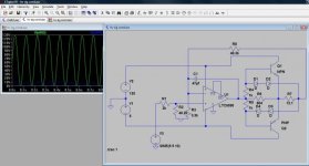
hvsigcond.jpg
 
Ouch. Ya know, I'd be proposing a capital plan to eliminate all of those unsupported 'custom' boards and such.
A simple application like that, just managing the lay with a traversing takeup would need two two-axis controllers, or one four axis controller:
One axis for the rotating cage (reference axis)
One for the capstan (slaved follower)
One for the takeup reel (reference axis)
One for the travese (slaved to takeup).

I have a project similar, but with a much larger cabler, with 10 synchronized payoffs, two tape heads, capstan, and takeup. I found that using Delta Motion RMC controller to be a relatively inexpensive option to replace the existing synchronization system.

You could get by with two RMC70's I'd imagine, and wouldn't have to do the cabler/capstan and the takeup/traverse at the same time.
 
That sounds like a lot of fun, but it's a bit of a delicate situation. I'm a self employed one man operation, and this is for a relatively new customer. This customer is a small-ish, low-budget company. After a handful of incidents of DC motor & drive failure, and waiting for rewind shops, they have made it a goal to replace all the DC motors and drives (one at a time, as monetary & down time budget affords) with more up to date technology that can be replaced off-the-shelf same day instead of incurring several days of downtime.

As I said, my relationship with the company is in its infancy and I have to do everything in my power to present myself as an ethical person/business. I have a strong suspicion that proposing such a sweeping modification (replacement of everything in the cabinet except main breaker) would appear to them the same as if you took your car into the mechanic to get a brake upgrade and the mechanic told you that you need a new engine, transmission, and differential, plus be without a car for at least a week. I'm afraid I could lose the job, and probably all future jobs. You and I both know that the two scenarios are not equivalent, but think of it from their point of view; they would likely see it as equivalent. For the time being, I'd like to provide only the services that were requested (AC motor & drive retrofit), as easily, quickly, and cheaply as possible, with the least extraneous work as possible. In the future, if there are any problems with their control boards, I feel that would be the time to propose the upgrades you've mentioned.

Thank you for the ideas and the information.
 

Similar Topics

I've got an older PLC that can't always pick up an input pulse from a sensor. The sensor is a pretty standard 24vdc PNP prox. I know I've seen...
Replies
8
Views
3,648
Hi , Where i can find Mitsubishi PLC Card end of line & replacement model details. i am looking for Q02CPU replacement model. Please advice. thanks
Replies
2
Views
126
I have Allen Bradley plcs, I have had Circuit breakers and other automation equipment in the past. There's no solid buyers local. How much do you...
Replies
2
Views
201
can anyone has a good program to learn plc programming online. i have the basic looking into improve my skills thanks
Replies
1
Views
144
I want to monitor a couple signals in a place where there is no PLC but there is ethernet. I know I can use an AENTR or Flex I/O and a module but...
Replies
21
Views
773
Back
Top Bottom