Pin Installation Machine

I looked at my #5 version and noticed some minor problems so have attempted to correct them in #6. I have not attempted the alarm situation because not sure what exactly is needed, as mentioned there are alot of "What ifs" but which need to be addressed and in what order I do not know.

This is version #6, hopefully it will help at some point. I think you said the project had to be running by tomorrow so I expect you have it mostly done by now.
 
I'm going in with several versions of the program to tryout. I've adopted much of what you supplied, as it is superior to what I came up with. Thanks for going above and beyond the call on this, Ron! I'll report back on how it turns out.

Paula
 
Well, today was a bit of an anti-climax -- didn't get far enough to test the program. Spent the day with final assembly, wiring, plumbing, and tweaking the alignment of the drill and driver. I did get as far as verifying all of the inputs, and dry-cycling the outputs. The vibratory feeder-bowl system works great, as does the photocell/fiber-optic system for spotting the tiny pin in the driver nosepiece. Tomorrow morning I will finish aligning the drill and the index table, and will then be ready to test the program.

Biggest "oops" so far is the absence of a system for handling the (eventual) drill chips. It seems to be the favorite comment from casual observers. Me: "Er, ummm... <heh, heh>"
embarassed.gif


More to come...

Paula
 
As far as the drillings go, a shop vac might be the ticket. If you can control the feed of the drill, you should be able to assure you get chips rather then long coils which may clog the vaccume.
 
One of the reasons I attempted to assist is because I have previously done a system similar to this. I "assumed" since you were a mechanical engineer that situations like this were covered....ooopppsss again.

I agree that a shop vac or equivalent may work but it depends on how the system is physically designed if that is the most viable solution.

It may be possible to just let the chips fall into a container OR use a pusher (ram) to push them off the table into a container.

If you get a chance and can take a picture of the machine maybe we can offer alternatives.
 
I used to work at a manufacturer of multi spindle drilling equipment and chip management was one of the toughtest things to handle. This is especially tru when you have 8 or 16 or 64 drills making chips at once.

I can't tell from the sketches so far what the scale of this thing is. The shopvac will work up to a point and is probably ok. As previously mentioned, the chip formation can be an issue and will be determined by many things including feed rate, drill RPM, part material and hardness and drill geometry.

One of the bigest "gotcha" issues I see is the question of what happens to the pin insert when some chips are left in the hole. Depending on the pin and driver, this may or may not be an issue.

The next is how critical is hole location? As chips start to pile up on the fixture, the part will not be resting tightly up against the locating surfaces. Also, chips could scratch the finish on the part.

Some of these issues go away if the part is manually loaded and there is an operator there for every cycle (I think this is the case). Then again, not all operators are as attentive to detail as we would like.

The ideal situation is to have a continuous stream of coolant on the drill/part interface but I think you don't need that here. You might want to put an air nozzle with a valve in and shoot a blast of air at the end of the cycle to blow the chips off to top of the part so they don't fall on the fixture when the part is unloaded.

Making one part is easy; it's the making of 1000's of parts where the chips really start to pile up.

Good Luck
 
Thanks for the ideas, you guys! I wasn't mentioning the chip-handling omission in hopes of getting a solution here, but more for injecting a bit of levity into the day's account. It's not really a problem -- the material is 360 brass, so the chips are small and flake-like, and can simply fall through a hole in the fixture base plate, into a container. Also, the locating portion of the fixture is designed such that drill chips will not pile up and cause registration problems. I will post some pictures later on to give a better idea.

Paula
 
ndzied1 said:
One of the bigest "gotcha" issues I see is the question of what happens to the pin insert when some chips are left in the hole. Depending on the pin and driver, this may or may not be an issue.
I've done a lot of multi-station machines and learned a good rule of thumb. You pretty much need a station for every operation and ANOTHER station to check that every operation got completed properly.

For example, if Paula's machine was on an assembly line or rotary table, and chips being left in the drilled hole was an issue, you would want to check for chips with maybe an LVDT (linear variable dispacement transducer) probe. This would insure that you could insert the pin far enough to make an accurate part.

Of course, simple operations or multiple simple operations could be checked later in perhaps one stage, but why put more cost into a part that you already determined to be scrap? This opens a whole new lesson on shift registers for tagging reject parts to discontinue further operations after a defect is found. The "tagged" reject parts trigger an ejection mechanism at the unloading stage based on the bit conditions of the shift register.

Man, I love controls...
 
I'm just trying to get this project completed on time so I can get caught up on three other jobs I've either started, or have waiting in the wings. ...It's just not a good time to start trying to wrap my brain around a different type of programming.
An intelligent designer always considers how the customer's needs (Paula's need for a fast program in this case) relates to what the engineer knows how to do. If you know a great and glorius method, but it is not usable by the customer, then it is not the best solution for your customer, even though it might be the best from your viewpoint!
I'm limited to a single Fault lamp, connected to Y10. My plan is to add logic where appropriate to determine when a particular event doesn't happen within a reasonable time, and turn on the Fault lamp (and halt the cycle) when the time expires.

Paula, I have a Directsoft routine for alarms that uses ONE light output to indicate exactly which alarm is being triggered. It works well for up to about 30 alarm points. The method consists of setting up two counters, with two-digit codes, which are blinked in sequence. I have posted the routine in the "Downloads" section of this forum. Using this routine, your operator will not have to guesss what the alarm light means. He can have a printed card with a list of the alarm codes taped to the machine.
 
Hi all,

Following up on the machine progress...

After finishing up with adjustments to the drill and driver, I downloaded the program to the PLC. There were some problems at first, minor ones really, but eventually everything worked beautifully! The logic for the drill cycle that Ron wrote works especially well -- thanks Ron! It turns out that I did need to seal in the X4 (clamp extended) contact with the Y3 (drill start) coil, because of the pressure drop when the drill starts, but that is a minor thing.

I wound up placing the logic for feeding the pin immediately following the 'start' rung, as it seemed to work the best. With this arrangement, the clamp actuates immediately on pressing the Start button, and the drill starts as soon as the clamp is extended. The pin feed cycle occurs during the drill cycle, with the pin arriving at the driver well before the completion of the drill cycle. I changed the last couple of rungs slightly, as I want both the clamp and the table to begin retracting as soon as the driver is retracted. This eliminates some needless waiting on the part of the operator.

Apart from the program, which works great, there is an issue with the drill bit. The one supplied to me by the customer is one that they had made up to use on their CNC machining center. It is a solid carbide, straight-flute drill bit, with a heavy web thickness, and zero rake on the cutting lips. It reportedly does a fine job in their machine, running at 8000 RPM, but is not working so well with the little air drill running at 2800 RPM. It almost seems to "burnish" its way through the brass, and leaves a huge burr on the exit hole. Substituting a #43 HSS screw-machine drill bit does an excellent job of drilling, though it is slightly off-size. I informed the customer of this problem nearly a month ago (when I first ran some trials with the air drill), and he agreed to "look into" getting a more suitable drill bit made up, but he has yet to do so. I suspect that now that they need to actually start using this machine, the problem will get resolved fairly quickly.

All in all, this has been a very rewarding project, and I'm extremely grateful for the help offered by the PLCS forum members. Especially Ron, who obviously spent a good deal of time working out the details of the program. I took some pictures of the machine before leaving Friday:

PINSTAL3.jpg


PINSTAL1.jpg


PINSTAL4.jpg


PINSTAL2.jpg


Thanks again to all who contributed!

Paula
 
Hi Paula,

Although I haven't posted, I have been following this thread. Thanks for posting pictures of your creation.

Congratulations on a job well done - the machine and panel look great.
 
Problem with modification

Hi Guys,

This is a follow-up on the status of the Pin Installation Machine, and a question about a modification that I just made to it.

Recently my customer figured out a way to drill the hole for the pin on the CNC, and asked me to modify my machine for feeding and pressing in the pin only. Obviously, they could have done it by simply removing the drill bit from the self-feed drill, but they wanted me to "optimize" the machine for fastest cycle time.

So, I made some mechanical modifications to the machine, and greatly simplified the PLC program. The sequence of operation now reads as follows:

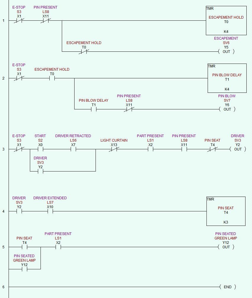
1) With the machine powered up, the operator pulls out the STOP button, and presses the RESET button, activating the MCR.

2) If there is no pin in the nosepiece (X11), the escapement cylinder (Y5) is energized for .4 seconds (T0).

3) After another .4 second delay (T1), the Pin Blow valve (Y6) is energized until the pin arrives at the nosepiece (X11).

4) The operator places a part in the fixture, and presses START (X0).

5) If the part is detected in the fixture (X2), and there is a pin present in the nosepiece (X11), the driver cylinder is energized (Y2), pushing the pin into the hole.

6) Once the driver is extended (X10) for .3 seconds (T4), the driver is retracted, and a green lamp (Y12) is illuminated.

7) The operator removes the finished part from the fixture, and the lamp (Y2) goes off.

Here is the program I came up with:

PINONLY1.jpg


This program works well, and the customer is very pleased with the 4-5 second cycle time. But there is a glitch in the program that I am unable to figure out. Whenever the control system is powered up with no pin in the nosepiece, the pin-feed sequence does not work. The Pin Blow valve (Y6) is energized, and just stays on, as though the Escapement step is bypassed.

If the driver (Y2) is then manually cycled once, the pin-feed sequence works properly from then on.

This is not a huge problem, since it only happened the first time I powered up the system (and the nosepiece was not "primed" with a pin), and after that only when they inadvertantly let the bowl run dry. But I feel like it's something really simple, and I'd like to fix it.

Anyone have an idea?

Paula
 

Similar Topics

Hello: I have to connect a RS232 Modbus RTU slave that only has Tx, Rx and GND signals to a Modbus RTU master. However, all RS232 to RS485...
Replies
3
Views
227
Hi All, I came up with this for ramping the PWM pin on the micro 820. I'm new to ladder logic so I am not sure if this will even work? Once...
Replies
6
Views
341
MELSEC A RS422 (25pin) <> iQR C24 Serial RS232 (9pin) - Simple PLC Communication Communication from a MELSEC-A Series CPU (RS-422 – DB 25 Pin)...
Replies
4
Views
1,036
M12 sensor plugs are widely used. I'm about making my own CAD symbols for sensor connections, and I'm not sure about including pin #5, which is...
Replies
6
Views
1,489
In my FC I use an inout variable for the memory of a Set/reset. When i call the FC i have the pin at the entry side of the block while i would...
Replies
4
Views
1,917
Back
Top Bottom