Utilizing a Timers Transistor Output

🙃
Yowww, dmargineau, you just got burned :whistle: ;)

Just to add that Mitsubishi drives are the same.

It seems that my point did not go through...Trying again...🙃

The provisions of external power supply are not there for one to use a straight PLC output to control a self powered third party device; it will work as such, however, it is not a safe, efficient and functionally sound integration. The separation between Control and Controlled is a fundamental principle of controls theory.

THEY MAKE RELAY OUTPUTS FOR THAT PURPOSE!.

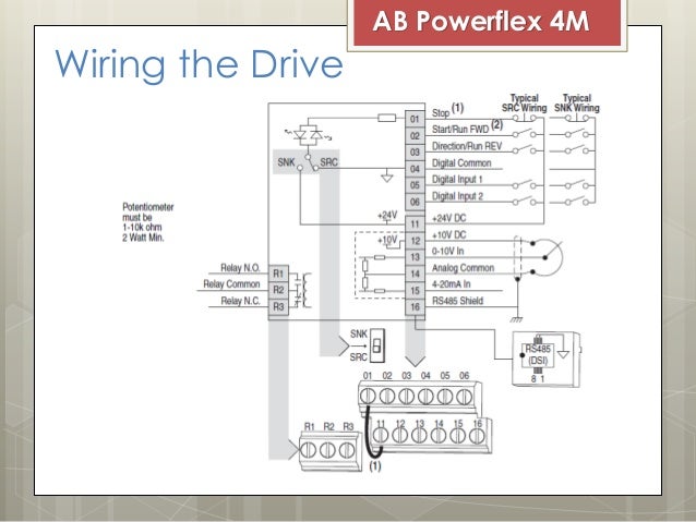
The OP asked about connecting the DI circuitry of a VFD to some timer device transistor output;...You need an Interposing Relay was my answer...That's the way it's been done since the inception of electrical controls...Rigging up and making it work without considering of all the caveats is amateurish at best...My $ 0.02...:D
 
I think the problem is that maybe not everybody realizes that a standard PLC transistor source output (aka PNP output) is the equivalent of a normally open relay contact to power supply 24V?

They look at the examples in the user manual and think it has to be a relay because that is what the manufacturer used in their symbolic sketch? I'm just guessing here.

output_source.gif


Or that every manufacturer is using isolated inputs. Usually with opto-couplers (aka optoisolators) so that there is a electrical separation between VFD inputs and VFD internals.

Everyone 'realizes' that...It's seventh grade physics...The point is not electrical functionality but controls theory...
 
I think you may need to point us to some documentation that provides us with some guidance to meet your wildly general statement of "The separation between Control and Controlled is a fundamental principle of controls theory."
 
I think you may need to point us to some documentation that provides us with some guidance to meet your wildly general statement of "The separation between Control and Controlled is a fundamental principle of controls theory."

Look into your textbooks...If ever any...:D
 
Thanks, i will go with the majority on this one and the manufacturers of the drives/devices and use the signalling as designed rather than refer to some books you can't even be bothered to list........ 🍺

🍺...same to ya...🍺

Keeping different manufacturer and/or various functionality devices power supplies separate is a professionally good practice; taking out control voltage when you lose a VFD's mains is mandatory for a safe and functionally sound application; merely stating that 'it works' does not make it right when looking at the big picture of an automation system.

Let's leave it here...Run your PLC power into VFD's if you wish...:D
 
CAAJ (the OP): Please provide the model number of your VFD.

Pete S.: Post #14 shows an example for PNP. The OP shows a NPN module in post #1.
Post #12 shows common going to input #4 - that looks wrong.

dmargineau: Please review and correct your answer in post #6. Terminals 0 and 5 are the Emmitter and Collector of an NPN transistor. It will not provide power for the relay, only contact closure.

Too all:
Posts #10 and #13 provide examples of NPN. Someone please provide a schematic showing the OP's NPN module connecting to a typical VFD.

The VFD inputs are optoisolators. You can and should use the PLC power supply to drive them with PNP outputs. With NPN or relays, use the VFD supply to power the opto + input, and the PLC NPN or interposing relay to supply the 0V.
 
That is correct; the transistor output will energize a properly rated interposing relay coil; the VFD's control power lead will connect to one side of one of the relay's Normally Open contacts and the Start configured VFD on-board Input lead will connect to the other side of the relay's NO contact.

When the timing device will energize the relay's coil the VFD will receive a Start command.

As mentioned previously and too late for editing the above quoted answer the coil of the 24VDC rated interposing relay will represent the LOAD of the posted circuitry...There is no need for PNP or NPN observance when using an interposing relay.
 
Last edited:
🍺...same to ya...🍺

Keeping different manufacturer and/or various functionality devices power supplies separate is a professionally good practice; taking out control voltage when you lose a VFD's mains is mandatory for a safe and functionally sound application; merely stating that 'it works' does not make it right when looking at the big picture of an automation system.

Let's leave it here...Run your PLC power into VFD's if you wish...:D

The VFD inputs are always galvanically ISOLATED. Please look that up if you don't know what that means.

This is done by adding an optoisolator which basically works like a relay but instead of using magnetic force it uses light.

The only thing adding interposing relays does is adding a component that is not needed and lower the reliability by inserting an electro-mechanical device in the circuit.

What you are proposing is simply bad practice. It made sense back in the days when we used AC mains as control voltage and things that needed 24VDC for control started to appear.
 
CAAJ (the OP): Please provide the model number of your VFD.

Pete S.: Post #14 shows an example for PNP. The OP shows a NPN module in post #1.
Post #12 shows common going to input #4 - that looks wrong.

dmargineau: Please review and correct your answer in post #6. Terminals 0 and 5 are the Emmitter and Collector of an NPN transistor. It will not provide power for the relay, only contact closure.

Too all:
Posts #10 and #13 provide examples of NPN. Someone please provide a schematic showing the OP's NPN module connecting to a typical VFD.

The VFD inputs are optoisolators. You can and should use the PLC power supply to drive them with PNP outputs. With NPN or relays, use the VFD supply to power the opto + input, and the PLC NPN or interposing relay to supply the 0V.

I agree. I used PNP as examples since we started talking about PLC outputs in general. In the west these are commonly PNP aka source outputs.

Regarding post #12. It looks right to me. It's from the manual. Common is the common 0V of all the optoisolator inputs (LED side / cathode).

Some VFDs support both NPN and PNP for instance AB Powerflex.
If you connect an transistor NPN output to one of these you have to switch it to SNK.
As you can see that connects the LED of the optoisolator to internal +24V.
Then Digital common goes to 0V and the transistor output to the input.
ac-drive-vfd-allen-bradley-powerflex-4m-2-638.jpg


PS. If the OP wanted to connect a NPN transistor output to an input made for PNP outputs. He could use a pull up resistor from the power supply of the VFD to the input. Problem is finding the right resistance for that as you don't want to draw too much current from the NPN output but you must have enough current to drive the input when the transistor is off.

I think it's not advisable for industrial control and agree with dmargineau that he should use a relay. Or a NPN to PNP module. Just because most electricians expect sourcing outputs and inputs.

I think NPN is more commonly used in Asia. I'm not sure. It's pretty common in electronic design though but we usually call them open collector outputs.
 
Last edited:
The VFD inputs are always galvanically ISOLATED. Please look that up if you don't know what that means.

@Pete.S. Please refrain yourself from preaching to the wrong choir...

A research of your posts actually points to the need of you belonging to a choir rather than preaching to one...:D

Interposing relays have been around as long as automation existed and will be around for a while...They serve a specific purpose and optical/galvanic isolation of any Input and/or Output devices is not related to said purpose.

Modern control systems use Relay or Isolated Output modules (the young 'cousins' of the Interposing Relays)... Have you ever seen one?...Have you ever read any major manufacturer electrical automation specifications?...Do you think they call for 'dry contact' interfaces because they just look for trouble or don't quite know how to run a business?

Matching a PNP/NPN combination of PLC modules and third party devices digital circuitry is a waste of time and resources; running PLC control power out in the field is a bad practice. A Relay Output will control ANY rated voltage, AC, DC (PNP and NPN), Digital(0-5VDC), Analog, etc. allowing for safe and efficient use of the allocated I/O.

All VFDs have internal control power supplies; some do not have external power supply provisions.

Let's leave it here...Maybe after a few rounds around the block you'd come to a different conclusion...Or not...:D
 
🍺...same to ya...🍺

Keeping different manufacturer and/or various functionality devices power supplies separate is a professionally good practice; taking out control voltage when you lose a VFD's mains is mandatory for a safe and functionally sound application; merely stating that 'it works' does not make it right when looking at the big picture of an automation system.

Let's leave it here...Run your PLC power into VFD's if you wish...:D
Have to disagree with you also. Running control power to VFD inputs carries no more risk than firing a motor starter coil with the same control power. Not sure what you're worried about here.
 

Similar Topics

Hello, I'm trying to solve this problem for the batch mixer simulation. As shown in the picture, I have a "no motion rung" set up as a OR logic...
Replies
2
Views
1,596
Hey guys, I need some help, as I am VERY confused. I am merely trying to track bottles on a conveyor line using a Bit Shift function, with a...
Replies
23
Views
9,593
I am programming an HE-XE102NR with CScape 9.6. I have imported my recipes via the recipes editor. The one thing i can't seem to figure out is how...
Replies
3
Views
1,638
Hi, I'm quite new to Rockwell PLC and currently trying to implement the following if Sw1 then for i:=1 to 20 by 1 do xEnable := 1...
Replies
9
Views
368
I'm writing some alterations to an FPWin program and need to see the running value of timers so I can set them correctly. It's my first time with...
Replies
0
Views
131
Back
Top Bottom