Utilizing a Timers Transistor Output

CAAJ

Member
Join Date
Dec 2014
Location
Fairhaven, Ma
Posts
47
Hello All,

I need a bit of help utilizing a timer's DC transistor output to start/stop a motor with a VFD.

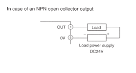
The motor currently being utilized has a VFD which can be started and stopped by closing the circuit between an on board 12VDC reference terminal to an on board Digital input start/stop terminal. However to provide control over operation time, I would like to utilize a timer to stop the unit after a set amount of time, thus opening that circuit. I would like to utilize the timer's transistor output to power the digital input on the VFD, however I do not know how to properly utilize the transistor on the timer. The diagram attached seems a bit confusing to me when trying to compare with my application.

If anyone could please lead me in the right direction, it would be greatly appreciated.
:D:D:D

Thank you for your time!

timer transistor diagram.PNG
 
Hello All,

I need a bit of help utilizing a timer's DC transistor output to start/stop a motor with a VFD.

The motor currently being utilized has a VFD which can be started and stopped by closing the circuit between an on board 12VDC reference terminal to an on board Digital input start/stop terminal. However to provide control over operation time, I would like to utilize a timer to stop the unit after a set amount of time, thus opening that circuit. I would like to utilize the timer's transistor output to power the digital input on the VFD, however I do not know how to properly utilize the transistor on the timer. The diagram attached seems a bit confusing to me when trying to compare with my application.

If anyone could please lead me in the right direction, it would be greatly appreciated.
:D:D:D

Thank you for your time!

Unfortunately, in order to use the VFD's on-board circuitry for drive commands you will need an interposing relay; the interposing relay will isolate the VFD's circuitry from the control one while providing the intended functionality.

The VFD's control power will be switched into an Input via the interposing relay's contacts while the timer device will control the interposing relay's coil.

Usually the PLC output can drive the VFD inputs directly - if the 0V is common. So you have to connect 0V on the VFD to 0V on your PLC output module supply.

The internal power supply available on VFDs is just for convenience when connecting push buttons.

Above being true when you have source outputs (PNP) on the PLC / timer / whatever. It looks like the schematic above is a sink output.
 
Usually the PLC output can drive the VFD inputs directly - if the 0V is common. So you have to connect 0V on the VFD to 0V on your PLC output module supply.

Usually?!...Not true...PLC Relay (Isolated) Outputs usually drive VFD's...A three phase VFD 'produces' its own control voltage...which is needed to switch the on-board Inputs...via a dry-contact device (PB or Relay)...Some highly priced devices provide Separate Control Power Supply provisions, however, I have yet to see a PLC Output module sharing control power with a VFD...But then again...Everything is possible in an alternative world...:D
 
Unfortunately, in order to use the VFD's on-board circuitry for drive commands you will need an interposing relay; the interposing relay will isolate the VFD's circuitry from the control one while providing the intended functionality.

The VFD's control power will be switched into an Input via the interposing relay's contacts while the timer device will control the interposing relay's coil.

So I would need to use a mechanical relay that's coil is rated for DC voltage? If that is the case would I simply connect terminal 5 and terminal 1 to the coil?

Thank you again for the feedback!

CAAJ
 
So I would need to use a mechanical relay that's coil is rated for DC voltage? If that is the case would I simply connect terminal 5 and terminal 1 to the coil?

Thank you again for the feedback!

CAAJ

That is correct; the transistor output will energize a properly rated interposing relay coil; the VFD's control power lead will connect to one side of one of the relay's Normally Open contacts and the Start configured VFD on-board Input lead will connect to the other side of the relay's NO contact.

When the timing device will energize the relay's coil the VFD will receive a Start command.
 
Usually?!...Not true...PLC Relay (Isolated) Outputs usually drive VFD's...A three phase VFD 'produces' its own control voltage...which is needed to switch the on-board Inputs...via a dry-contact device (PB or Relay)...Some highly priced devices provide Separate Control Power Supply provisions, however, I have yet to see a PLC Output module sharing control power with a VFD...But then again...Everything is possible in an alternative world...:D

When I say "usually" it's because I haven't used every type and model of VFD under the sun. But on the ones I have used since the 80s you don't need relay outputs or intermediary relays to drive start/stop signals from the PLC.

I've met several Electrical Engineers that have the same misunderstanding as you, so you are not alone.

PS. If you know a VFD that you believe can't be controlled directly from a non-relay output from a PLC, please post the make and model. You might be right that these exists.
 
Last edited:
I've met several Electrical Engineers that have the same misunderstanding as you, so you are not alone.

There are no misunderstandings here...The separation between power and control circuitry concept has been around since the XIXth Century (19th for alternative facts fans)...We are now in the XXIst (21st)...There is a reason every PLC manufacturer provides Relay (Isolated) Outputs....Because that's how a PLC controls third party devices with own supply power...I would be very interested to know more about the almost forty years old VFDs types still going as we 'speak' and the PLC platform controlling said inverters with straight outputs...A wiring diagram will be also helpful...Just to enlighten myself and other members about you particular approach...:D
 
Just in case . . .
When one is operating a dc relay with a transistor output, it is usually a good idea to add a diode across the output - reverse biased. So that when the output opens and the coil voltage 'collapses' the inductive 'kick' has someplace to go. (Rather than spiking the transistor.)

>>>
"With a transistor output driving a relay, a freewheeling diode is absolutely necessary, because the voltage spike will destroy the transistor."

https://electronics.stackexchange.c...ck-diode-with-an-automotive-relay/56323#56323
>>>

MadPoet.
 
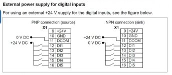
Here is part of a page from an ABB ACS355 manual, you can use either the internal 24V supply, or an external one, obviously not both at the same time. The same way you can use the internal 10V supply to power a 10K pot that drives the analogue input, or you can take the 0-10V signal from a PLC analogue output. I have seen cheaper VSDs that only allow you to use the onboard voltages and potentiometer, but that makes it difficult to get a PLC to control the speed. We have had a few people on here asking for a method to convert 0-10V to a 10K resistance.

ABB External supply.jpg
 
Here is part of a page from an ABB ACS355 manual, you can use either the internal 24V supply, or an external one, obviously not both at the same time. The same way you can use the internal 10V supply to power a 10K pot that drives the analogue input, or you can take the 0-10V signal from a PLC analogue output. I have seen cheaper VSDs that only allow you to use the onboard voltages and potentiometer, but that makes it difficult to get a PLC to control the speed. We have had a few people on here asking for a method to convert 0-10V to a 10K resistance.

Yowww, dmargineau, you just got burned :whistle: ;)

Just to add that Mitsubishi drives are the same.
 
Last edited:
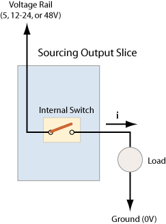
I think the problem is that maybe not everybody realizes that a standard PLC transistor source output (aka PNP output) is the equivalent of a normally open relay contact to power supply 24V?

They look at the examples in the user manual and think it has to be a relay because that is what the manufacturer used in their symbolic sketch? I'm just guessing here.

output_source.gif


Or that every manufacturer is using isolated inputs. Usually with opto-couplers (aka optoisolators) so that there is a electrical separation between VFD inputs and VFD internals.
 
Last edited:
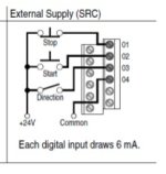
Some of AB's drives can use external power to their control inputs instead of the onboard-generated control voltage.

I have, on one previous occasion, used the 24V generated by a PowerFlex 4 to power the photoeye and electronic timer of a small standalone conveyor. There was no need for an interposing relay in this scheme since all of the 24V was generated by the VFD.
 

Similar Topics

Hello, I'm trying to solve this problem for the batch mixer simulation. As shown in the picture, I have a "no motion rung" set up as a OR logic...
Replies
2
Views
1,592
Hey guys, I need some help, as I am VERY confused. I am merely trying to track bottles on a conveyor line using a Bit Shift function, with a...
Replies
23
Views
9,590
I am programming an HE-XE102NR with CScape 9.6. I have imported my recipes via the recipes editor. The one thing i can't seem to figure out is how...
Replies
3
Views
1,637
Hi, I'm quite new to Rockwell PLC and currently trying to implement the following if Sw1 then for i:=1 to 20 by 1 do xEnable := 1...
Replies
9
Views
363
I'm writing some alterations to an FPWin program and need to see the running value of timers so I can set them correctly. It's my first time with...
Replies
0
Views
131
Back
Top Bottom