Mitsubishi Alpha2, how to ramp up a voltage?

The_spider

Member
Join Date
Dec 2022
Location
Earth
Posts
2
Hi, i hope somebody here could assist with this problem?

we're looking to provide another piece of equipment with steadly increasing voltage from 0v to 3v, increasing at a preset rate of ~10mV/sec.

we already have a mitsubishi alpha2 fitted with an analogue output module, could this be made to do the job?

thanks in advance!
The_spider
 
Never used one of those but looing quickly at the manual it should be easy.
There is an analogue output function that takes an integer value & outputs it to a channel on the analog output channel, all you need to do is increment the digital representation of the value to this block.
Not looked at it closely but perhaps use a timer pulse to add x number to a dataword every 10ms.
subtract the value if you need to ramp it down, there may be even a ramp up/down function but the above would be just as easy.
Again not looked at the analogue card but assume it could be either 0-10v or 4-20ma or even both perhaps pin selectable. you would need to find out what the raw digital value needs to be for 3v & probably limit it to that.
lets assume 0-1024 was 0-10v then if you wanted increments of 100mv that would be add say 102 to the variable integer value 102.4 c
For 10mv increments then it would be 10.24 (but it is probably only integer so increments of 10 or if the Alpha does floats then you will need to increment the float then convert it into an integer.

here is the manual:
https://dl.mitsubishielectric.com/dl/fa/document/manual/plc_fx/jy992d97101/jy992d97101g.pdf

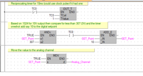
Below is a way, however, this is not alpha but you can see how to do it, if you need to decrement it just subtract from it
you will need some contact in the second ladder to control when it increments it and perhaps decrement it or perhaps just put it to 0.

Analogue.png
 
It seems that for 0-10v is 0-4000 so at 3v it should be 1200
Horrible software, the popup descriptions of the tools does not work most of the time, when forcing say a counter you change the value press write to plc & it brings up a second box for the same thing.
 
What @parky said:

It looks to me like the [M03] system bit cycles at 1Hz, so it has a rising edge once per second, so a program could

  • Use a [Counter block with a preset Count of 300]
  • Use an [AND] block, and connect three inputs:
    • that M03 bit,
    • [I01], the input signal (switch, button) that the analog output should be ramping up,
    • the third and fourth output pins are unused and considered to be ON.
  • Feed the output of that [AND] to the Input pin of that [Counter block] above,
    [*]Use a [Multiply] block with
    • Input A is the DirectSet (Constant Value) of 4*,
    • Input B is the [4.b) Current Count] of that [Counter block] above,
    • Output Y goes to the word input pin of the [Analog Output block] below.


    [*]Use a second [NOT] block to invert the [I01] input signal
    • so releasing the [I01] input signal resets the Current Count of the [Counter block] above to 0,
    • as well as the analog output to 0,
    • and the analog output's voltage to 0V.


* 4analog counts = 10mV × (4000analog counts / 10V) × (1V / 1000mV)
 
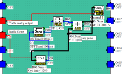
Here is a quick & simple way to increment the analogue signal.
input 0 not used, input 1 enables the analogue output otherwise it is 0 (disabled you could put a true on here to enable it all the time)
Input 2 is the count up enable, this enables the flicker function at the moment this is set at 100ms but could be set at any value this feeds the pulse (oneshot function so it is only on for one scan.
The flicker is enabled by a compare so if the count is less than 1200 (3V) then it adds 10 to the count everytime the flicker triggers the count (ADD Function) sends the digital value to the analogue function.
Note: the spare input on the analogue function is to switch it from 0-10v to 4-20ma so left disconnected it defaults to 0-10v.
I have not done any logic to reset or decrement the count it would be a good exercise to sort that out.
This software is very buggy, hard to use, functions are not documented very well, I would prefer to use say an FX range plc.

Analogue.png
 
Thanks guys, that was a quick responce! now we just need to put it into practice and try something.

i think drbitboy's suggestion idea of manualy giving a input (I01) for the duration of the process is a good idea, the equipment will never run unattended; the rising voltage is going to be used to control a constant current supply for a hysterisis brake that we're useing in conjunction with torque transducer, its basicaly a Dyno for small brushed and brushless DC motors.
we're currently increasing the voltage of CC supply manualy

any other ideas/screen shots would be greatfully received!
i'll try and post some footage when its up and running
 
The enable on my last post does that, so perhaps a start/stop latch would be used, the only thing you need to do is find some way of resetting the accumulated count, I tried using a counter but it seems that if you link the count pin to the analogue it takes the preset value not the actual, if you set the preset to 0 the counter does not count so that is why I used a variable by incrementing it. Not tried an up/down one though.
 
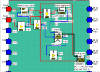
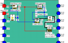
Here you go, pretty simple but as this software is a bit buggy on simulation I could not get an up counter to output the value to the analog, it did work once but it seems to work well on an up/down counter (hope this is not a bug in actual plc).
So, we have two inputs i.e. a start/stop buttons, the stop button is normally closed (standard convention) if N/O just remove the NOT function.
When started, it enables the pulse generator (Flicker this is set at 10ms) this feeds the counter, the counter value is output to the analogue, there is a counter preset (double click on the Counter) this is set at 1200 the count for a value of 3V. when the counter reaches this value the counter boolean output disables the flicker. pressing the stop button resets the counter.

Analogue.png
 

Attachments

  • Analog1.zip
    2.4 KB · Views: 2
@parky paves the way again!

... it seems that if you link the count pin to the analogue it takes the preset value not the actual, ...

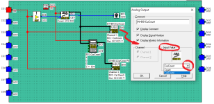
I all but stumbled :ROFLMAO: onto the solution for this while hooking up the calculation function block to an analog input: there is a drop-down select in the Analog Output Parameter Dialog, where we can choose the preset value or the current count; see the B09 analog output below.

Could it be more opaque?

This version uses the 1Hz M03 System Bit to trigger the B01 counter with a preset of 300, then the B03 calculation block scales the B01 current count by 4 and sends the result to the B06 analog output. The result is that the voltage will jump 10mV every 1s; for smaller increments over a shorter time increments, use @parky's approach with the flicker block to replace M03.

The counter automatically stops counting and ignores rising edges on the input pin when the current count reaches the preset value, so the output bit of the counter is not used for anything.

The I0n inputs are toggles in the simulator, so I got away with using only I01. The real application would need a Start/Stop Circuit, like @parky coded.

The B09 analog output is only there to show how to wire a counter's current count as the input to the analog output.
Untitled.png
 
Yes I did that, however, as I posted, first time with only up counter it was fine, but the pre-set value was 1000, I changed it to 1200 then it would not count, I think it must be a bug in the simulator, changed it to an up/down then it worked, just tried again & it works with an up only counter.
There are other bugs in the IDE, dragged a link line to make it a bit clearer, but it then tied it to another pin & messed up the whole logic as others had also done the same thing, perhaps it's win11 (why not blame that lol).
It is a poor system, when you drop a function on the grid it does not line up with inputs or other functions (noticed that on yours as well), there is a small offset, the right hand selection for the functions are small so a little hard to see what they are, when you hover the mouse over them they do not all show the text of what they are, the functions etc. when you drop them on the page are larger. In all quite buggy but I suppose for a small system & free software it's ok.
 
Refined it a little, did a multiply by 2 (could be any depending on how fast you ramp & by how much) Removed the counter up output & the not for the reset based on the fact that the stop button is N/C.

Analogue2.png
 
Nice! MUL block is a better choice than my CALCULATION block.

... it does not line up with inputs or other functions (noticed that on yours as well), there is a small offset, ...

I think they put that in there just to annoy me :ROFLMAO:.

Cheap-ish hardware, free software, I guess it's a market niche with customers who don't value time.
 
Last edited:
Yep, a little awkward to use & the manual is a little poor but I just loaded it on my Win 7 laptop & it seems to work a little better. I suppose once you get to use it then it becomes second nature so a little quicker.
 
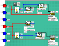
Got rid of the scaling block in the Flicker approach: see I04-driven blocks below; five blocks including the input (non-momentary switch); AO voltage increments 2.5mV every quarter-second to meet OP's desired ramp of 10mV/s.
Untitled.png
 
Last edited:

Similar Topics

Hello all I'm having a problem get the time clock function to be altered and displayed on got 1020 screen I've looked at the manual and It keeps...
Replies
1
Views
1,725
Hi, I need to program on a mitsubishi aplha2 series using function blocks. Any help will be greatly appreciated. here is the task The PLC is an...
Replies
0
Views
2,547
I'm looking to get some spare keys for this PLC. Does anyone know a source or have a part number? My searches are turning up nothing at the moment.
Replies
1
Views
57
I'm struggling to get an FR-E800SCE to work on CC-Link IE TSN. I'm sure the issue is with the drive, when I plug in the network cable I get no...
Replies
1
Views
88
Hi , Where i can find Mitsubishi PLC Card end of line & replacement model details. i am looking for Q02CPU replacement model. Please advice. thanks
Replies
2
Views
121
Back
Top Bottom