Flow Balancing Valves - Control Theory

I get all that. But OP also said the total flow could be selected by the operator.

Assuming that means there is some feedback control of total flow, e.g. perhaps via a VFD, and the sum of the 8 vessels' measured flows is the PV to that total flow feedback control.

So the goals are

  • run the selected total flow i.e. total flow SP,
  • run the VFD to meet that total flow SP with the minimum power requirement such that
  • the flow rate through each vessel is the same as the flow rate through all other vessels.
That being the case, sum of the 8 vessels' measured flow rates should be the same as the total flow rate PV, and since the total flow rate is under feedback control, that sum will also be the same as the total flow rate SP when that control is working. So the SPs for the individual vessels' flow valves should be 1/8 of the total flow rate SP.

Do I understand correctly that you are proposing to add feedback control of total flow, via a VFD (i.e. pump)?

Let the initial total inflow be 100 l/s. Setpoints for PID controllers of vessels / valves 12.5 l / s.
You change the total inflow setpoint to 200 l/s. The pump starts to increase flow but the flow through the vessels/valve rises so the vessel/valve PIDs start to close the valves.

If I understood the OP correctly, we cannot control the total inflow, i.e. it is disturbance.

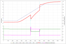
I applied the following "function":

If abs(70 – max(Valve1_position,… Valve8_position) > 0,5 then
SP := SP + 0,5 * dt * (70 – max(Valve1_position,… Valve8_position)
else
SP := SP

Curves below shows result

Qv1 – Vessel 1 flow (1/resistance = 0.1)
Qv2 – Vessel 2 flow (1/resistance = 0.2)
Qv8 – Vessel 8 flow (1/resistance = 0.8)
Q – total flow
SP – vessel/valve PIDs setpoint (Qv1-Qv8 curves almost covered by SP curves)
Valve1(2)_pos - Valve1(2) position
Vess8_SP.png
 
If I understood the OP correctly, we cannot control the total inflow, i.e. it is disturbance.

I understood the opposite:

moistcat said:
2. 1/8 of the total flow through each vessel is the same as fixed flow, as total flow can be selected by operations 10-200L/s.

My assumption, which may be invalid, is that operator selected implies controlled; how it is controlled I don't know, but a PID with that selected total flow as a setpoint sending its output as a speed reference to a VFD is not reasonable.

The problem with that is, if the total flow is available, then why bother summing the eight individual flows, then dividing that sum (instead of the operator selected total flow) by 8 to calculate the eight diff_flow values to be minimized to minimize inter-vessel variation?

Perhaps we do not know enough about the process.
 
Back in the dark ages,

Flow dividers in hydraulic power systems are currently in use and are likely to be used in the future.

they worked without power

Doing work without expending energy would violate the law of conservation of energy. The flow divider expends flow energy.

Would you like to apply the mechanism of the flow divider to solve the OP's issue? It would be very interesting to see
 
Last edited:
Flow dividers in hydraulic power systems are currently in use and are likely to be used in the future.
I know that but it depends on the application doesn't it? Flow dividers are cheap.


Doing work without expending energy would violate the law of conservation of energy. The flow divider expends flow energy.
I said nothing about expending energy. The flow dividers don't need electric power.


Would you like to apply the mechanism of the flow divider to solve the OP's issue? It would be very interesting to see
What issue? I don't see an issue,,,, yet.
 
Thanks all for the engaging feedback!
Operator selects flow set-point 10-200L/s, this is driven by bank of VSD driven pumps with flow transmitter on the outflow - working beautifully.

This then feeds into a number of parallel vessels that require even flow throughout. The parallel vessels all have the same topology:
Code:
INLETMANIFOLD-->--VALVE-->--VESSEL-->--FLOWTRANSMITTR-->--OUTLETMANIFOLD

The valve PID flow balancing initially works well,
SP = total flow / 8 (vessels)
PV = Flow transmitter
CV = Valve position

After flow is balanced, we may see the following valve positions (ill pretend 3 parallel vessels for simplicity):

VLV_A=99%
VLV_B=88%
VLV_C=50%

Now ill go and (partially) crank closed one of the manual hand operated valves on the vessel C, causing a restriction and thus flow imbalance.

Valves start actuating again, and flow is balanced at the following:

VLV_A=45%
VLV_B=60%
VLV_C=70%

Note that none of the valves are fully opened, but flow is perfectly balanced. My question was about creating a bias, so that at-least one valve was always at maximum position. (aiming to minimize unnecessary resistance to flow)
We have achieved this by adding a constant value 0.0x to the PV while no valves are > 90%.
 
Last edited:
Poormans P&ID

Code:
                                 |-valve-->--vessel-->--flowtransmittr-|
pumps-->--ft-->--inletmanifold-->|-valve-->--vessel-->--flowtransmittr-|>--outletmanifold
                                 |-valve-->--vessel-->--flowtransmittr-|
                                 |-valve-->--vessel-->--flowtransmittr-|
 
Thanks all for the engaging feedback!


And thank you for the extra info.

There seem to be two "total flow" values generated.

  • The sum of the eight flowmeters, one at each outlet of each of the eight parallel vessels.
    • Post #1 said this is the number that is divided by 8 to determine the base setpoint for the PID controllers of the eight valves.
  • The total flow from the transmitter that the VSD controls.
I am wondering why the control system uses the individual flows' sum, instead of using the single measured flow from the VSD pumps' outflow transmitter, to set the multiple individual SPs.

Not that it matters, since they should be more or less the same value, but I was just curious.
 
I am wondering why the control system uses the individual flows' sum, instead of using the single measured flow from the VSD pumps' outflow transmitter, to set the multiple individual SPs.

Not that it matters, since they should be more or less the same value, but I was just curious.

As the primary flow meter was faulty from factory and was out of service for a few months waiting for replacement :ROFLMAO:
 
Last edited:

Similar Topics

Hi, The hardware is: Click Plc model # CO-O1DD1-O HMI model # S3ML-R magnetic-inductive flow meter model # FMM100-1001. I will set the flow meter...
Replies
4
Views
90
Dear All, I need a sample PLC program to count the output pulse of a mass flow meter so that a specific amount of mass (for example 100gm)can be...
Replies
2
Views
134
Has anyone installed Hp laserjet pro 4203 to OMNI 3000 or 6000 via ethernet..Is there a specific Config? I have a problem..Please advise
Replies
0
Views
50
I can't seem to figure out how to add descriptors to I/O points on an RMC using PCCU. Say, for example, I want to use "Valve_1" as a descriptor...
Replies
0
Views
67
Greetings ... someone sent me a request for some student handsouts that I developed ... turns out that I had this hosted on my business website...
Replies
0
Views
123
Back
Top Bottom