Hey guys,
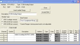
I have a problem that is puzzling me on a PLC 5 system. I am using a 4-20mA analog output (1771-OFE2/B) straight to a Powerflex 4m drive to run a small motor. This has supposedly worked before, but for some reason, all of a sudden we have no control over the motor. It just runs at a set speed.
Now, normally I would think that drive parameters were changed, to make it run off a preset speed, but that has been checked. The drive is definitely set for a 4-20mA input source signal. We have a pot, that is wired into the PLC, which gives us a speed setting(where the operator wants to run at). We manipulate it in the program for various reasons, and output this manipulated signal to the drive in the form of a 4-20mA signal. However, if we put a meter in series with the output, all we see is a never changing 12mA. And the drive runs at half its max speed, which I would expect it to do. However that is not what we are telling it to do. As we turn the pot, we see the value being written out to the analog card changing, we are just not seeing it physically change on the meter.
The BTR/BTW doing this, is in Ladder 4, on rungs 11 and 12. Whenever I click on the setup for these instructions, it displays a message saying something to the effect of "setup is not available/not configured". The values (2047) that the BTR is retrieving, do appear to be correct(half of 4095 being 12mA). It just doesn't seem to be writing out TO the card what we actually want the value to be.
Also, and this may be completely normal, if we put a scope on the output of the analog card, it doesnt display a smooth DC signal. It is more like a pulsating DC. We tried changing the analog card to no avail.
I have attached a zipped copy of the program in RSP format. Any help would be appreciated in explaining what is going on here!
Thanks


