Non-linear level measurements

Agreed, @#2 by LD piecewise linear interpolation probably least amount of work and "good enough."

And this is what the overthinking side looks like, modeling a cone-on-cylinder shape with Radius = cylinder height = cone height. Fifth order is good around one percent. The sine approximation is good to 5-10%, but may not work on OP's data, and would need at least third order to get to the 1% level. Chebyshev may do better; splitting linear and non-linear sections into separate sections may end up being exact; simplicity of PLC not an issue for polynomials, but still probably not worth the extra effort if linear interpolation is good enough, even if code will be ugly.
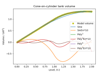
cvvplot.png
 
Nooooooo!
Why not divide the level into two ranges? There is a linear section that is easy to approximate. Then it will be easy to fit a second order equation to the non-linear section. A cone does not require a higher order polynomial to approximate it. Don't use a higher order than what is necessary because of the possible inflection points.
Fitting a polynomial to two different sections is folly for the reason I stated above.
Interpolation is much different that curve fitting and regression. They are two different things!!!

If you want to over think this then use cubic splines. It is also possible to do a local 3rd order interpolation using 4 data points and interpolating between the middle two. If the data points are equally spaced then the interpolation is relatively easy. If the data points are unevenly spaced use use Lagrange interpolation.
If you want to fit a polynomial to data then look at the Savitsky-Golay algrorithm
https://nirpyresearch.com/savitzky-golay-smoothing-method/
The S-G algorithm is a smoothing algorithm which is different from filtering or perhaps a subset of filtering.
 
Thank you for all the replies! I dont have the computer with the table with me this weekend.

I got this working nicely with a 2nd degree polynomial by writing a ladder code with the function, i put the coefficients and the constant into memory registers, so they can be changed without messing with the function.

I then split the tank table in two parts. 0-55% and 45-100%. Took a poly trendline on these two seperatly and used both in the program.

If level is less than 50%: i use the values of first part in the program.
If level is above 50%: i use the values for second part in the program.
 
Nooooooo!


Relax: it was not a serious proposal for the OP's case; rather a rabbit trail to investigate poly accuracy, and a sine model's accuracy, for a specific case; over the split ranges the polys will be near exact, as noted.


Not that it matters as this is not code golf, but I suspect the two-range poly is not much shorter, if at all, than the piecewise linear solution (unless FGEN is available for the latter). Neither wins a beauty contest.
 
Last edited:
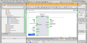
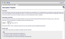
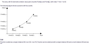
If you are using TIA portal then there is a function called polyline - once I had a tank which was created by merging two adjacent tanks, one of the tank was shorter the other one was taller so because of this the surface area initially was larger so the floating ball type sensor rises slowly but as you move up, the small tank is no more only the taller tank remains there the ball rises faster .

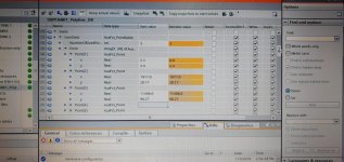
I used polyline function in TIA you can read about it in the documentations and implement the same formula- to use this I need to enter the set of points and the known value of measurement at those points as shown in attached picture

the x is the Int value from sensor and Y is the volume in BBL

download.jpg download2.png Screenshot_3.jpg Screenshot_4.jpg
 
Last edited:
The best PLCs should have a cubic spline cam table or similar. We have found these to be very handy for linearizing functions. The advantage of using a cubic spline is that it is similar to the simple linear interpolation between points but a cubic interpolation is used instead. This is MUCH better than trying to fit a 3rd or 5 order polynomial to a whole range of points. A cubic spline also makes sure the first and second derivatives are continuous at each data point.


Cubic splines are used all the time in motion control.
 
For everyone else, the best engineers can code cubic splines from first principles.


I doubt there are many that can. Originally we used Numerical Recipes in C. Later I bought two books on splines and graphics. Yes, graphics use splines to cover their wire frame images. Once one knows the trick it isn't that hard using Mathcad. Most people use a library or pre-made function block. I did a quick check and couldn't find a spline function written in structured text. Rockwell software has cam tables which use cubic splines. Our motion controller has cubic splines with enhancements. I have derived the code for 5th order splines but none of competition seems to use it and the customers don't require it so we haven't released it. The code has been commented out for about 15 years.
 

Similar Topics

Hello, I am seeing an issue with inaccurate tank level. It is an elliptical bottom tank with an Anderson Level sensor mounted on the bottom of...
Replies
20
Views
7,484
Hi All, Has anyone any experience in controlling a non linear valve with a PID? Traditionally this valve is controlled on flow but would like to...
Replies
36
Views
11,009
Hi guys and gals I have a severely non linear system that i am trying to develop a controller for. The non linear curve can be broken down...
Replies
8
Views
2,682
Hi, i have a pressure sensor (range 0-10 bar) and its output is 0-20 ma. but the current vs pressure curve is non linear such as. pressure...
Replies
3
Views
2,049
Hi all! I don't get a chance to get on this very often but I know this is a great resource for getting answers. Does anyone know where i can...
Replies
14
Views
3,877
Back
Top Bottom