ET200S 4F-DO config problem

cottagewood

Member
Join Date
Oct 2005
Location
Kent
Posts
179
Hi all
It’s been a while since I did any safety config with an S7-300 PLC and I think I must be missing something ,
I’ve added a 4F-DO output module (6es7 138-4fb03-0ab0) to an ET200S rack but I can’t clear the error light on it.
I’m 100% sure the dip switch setting matches the setting in the config.
I compiled and downloaded the config, I added the Acknowledgement for reintegration bit into the safety program along with the output.
I compiled and downloaded the safety program.
However the Acknowledgement for reintegration bit doesn’t go high and the error light on the card is always on.
I changed the card and the base but it’s still the same and my gut feeling is a config issue.

Has anybody got any ideas?
 
I second JRW, what do the diagnostics say?

What is connected to the outputs? Take a screenshot of the parameters.

, I added the Acknowledgement for reintegration bit into the safety program along with the output.
I compiled and downloaded the safety program.
However the Acknowledgement for reintegration bit doesn’t go high and the error light on the card is always on

Do you mean ACK_REI never goes high, or ACK_REQ never goes high?
If ACK_REI, check for duplicate write operations in the logic. If ACK_REQ never goes high, this is normal while the error is active.
 
Thanks for the replies

Under general Faulty module (diagnostic interrupt detected)

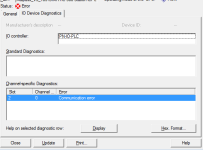
And under diagnostics it says communication error and the remedy it says check address parameter

screen shots attached

ACK_REQ

F-Param.png Error1.png
 
Last edited:
I've only done safety programming with an S7-1500 and ET200SP, which I'd expect to be quite different.
When I looked at the literature for safety outputs, it recommended using the FDBACK block (Again, don't know if TIA and Step7 will be different) which requires a feedback loop from the relay or contactor that you're activating (per SIL3 standards), which can use a non-safety DI.
It also required that any unused channels be deactivated. It took a bit of playing about to get the setup right and anything that it didn't like resulted in an error light.
 
That communication error is a tough one. I have cleared it before by separating the terminal blocks (backplane) and reseating them, but it always seemed a temporary solution.
Try resetting the Interface Module to factory settings and cycling the power before assigning the ProfiNet name.

Another way to clear it was to delete the rack and reconfigure it (yes, a pain). Step7 seems to prefer the modules are configured left to right. I don't have an explanation, but it worked.

Edit: is this a brand new module? The ones I have worked with are on training units, so they have suffered much use.
 
Last edited:
That communication error is a tough one. I have cleared it before by separating the terminal blocks (backplane) and reseating them, but it always seemed a temporary solution.
Try resetting the Interface Module to factory settings and cycling the power before assigning the ProfiNet name.

Another way to clear it was to delete the rack and reconfigure it (yes, a pain). Step7 seems to prefer the modules are configured left to right. I don't have an explanation, but it worked.

Edit: is this a brand new module? The ones I have worked with are on training units, so they have suffered much use.

The rack was existing and the output module was used before, however, when I couldn't get it to work they got another one from some one like Radwell and that was the same. It's possible that they are both faulty but it's unlikely.
I did contact Siemens and they told me to try lengthening the monitoring time, I haven't tried that yet but there are about 50 other fail safe modules on the system and they all have the default monitoring time of 150ms so I’m not holding my breath expecting that to make a difference.
As luck would have it, I found a spare unused output module on another rack, so I ran cables from that to get me out of trouble.
 
Something else to try:
In the CPU properties > Startup tab, adjust the "Monitoring Time for" both Finished messages and Transfer of parameters.
Adjust them one at a time.
 

Similar Topics

I was trying to communicate between Siemens ET200S IM-151-8 PN/DP CPU to Rockwell Allen Bradley L73 through Hilscher Gateway NT100-RE-EN. Using...
Replies
0
Views
110
PLC in the project that I am currently working on has following GSD file but I cant find it anywhere online. My PLC is ET200S and its CPU is...
Replies
7
Views
2,075
Got a new project using WinCC SCADA (V7.5 SP2) - the PLC is an ET200-SP, I've never had to communicate with one of these before (done plenty of...
Replies
3
Views
2,398
i m working on an old machine that has a layout of 1 cpu 6es7 315-6tg10-0ab0 (bus adresss 2) 1 et200s 6es7 151-1aa04-0abo (bus adress 4) 1 et200s...
Replies
7
Views
3,197
Hello Experts, I have two system one ET200S and another CPU 1513- PN which are 300 meters apart. Now i want to share data between these to...
Replies
8
Views
2,462
Back
Top Bottom