PLC Ladder Help 4 A newbie

trawets

Member
Join Date
May 2003
Posts
11
Wonder if anyone would like to help
This is a question I dont really know where to start to find the answer. I am very much a 'newbie', have only used basic dos programming software (TI).Would be grateful for a point in the right direction.Can anyone suggest a usable windows program, to write ladder diagrams.


A carpentry workshop has the sawdust created by two machines extracted through ducts by a three phase motor operating as an extractor fan. The system must operate to the following specification:
(a) The fan must run for 20 seconds before power can be supplied to either of the two machines.
(b) In the event of the fan motor overload protection operating, all the machines must stop.
(c) Only one motor can be switched on at a time, a 10 second time delay being required before the second machine can be started; the machines may be started in any order
(d) From the time that the last motor is turned off a 20 second delay is required before the exhaust fan may be stopped.
(e) Operating of the overload protection of a machine motor will only stop that machine as the workshop processes are independent of each other.

Task: implement the circuit using a PLC such that:
• The strategy proposed is effective
• The software designed is effective
• Demonstrate the operation at your PLC program
• Document ALL stages of the implementation:
• Show clearly your allocation of PLC inputs/outputs
• Draw a ladder diagram and relate it to a list mode version of your program or vice-versa
 
The first thing for you to do is to identify what brand of PLC your school is using for the hands-on lab exercises. Once you know that, you'll know which software package to use to write your programs. In fact, the school will probably make that software available to you.

If the school can't or won't make the materials available to you to complete your assignments, then you should be asking yourself exactly what are you paying tuition for.
 
All I know is that its a Texas Instruments PLC and the only software version is DOS based. I know this is functional but I thought maybe I could get a windows based program for working at home.
 
You still need to know which model TI PLC. Texas Instruments has been out of the PLC business for several years now. If it's a TI 305 or 405, those products are still available through Automation Direct as the DL305 and DL405 lines, and the Windows software for programming them is DirectSoft. I'll leave it up to the TI gurus to identify the name of the Windows package for the TI 500 series.
 
The second thing you should do (believe it or not), is to forget about the PLC programming software.

Although it will be very handy later to understand the "Instruction Set" (the functions that are available to use), this assignment can be done with just coils, contacts, and timers - which all PLCs have in their Instruction Set.

Your first task in this assignment is make a list of all the outputs that the PLC will control, and then a list of all the inputs that the PLC will get from the machinery and operators to so that it knows what to do next.

Your list of outputs is simple.

Your list of inputs will take some careful reading, and perhaps some decision making on your part. You should be able to answer the following questions with your Input list:

1) "In the event of the fan motor overload protection operating...." How will the PLC know this?

2) What operator control(s) will turn on each device (by controls, I mean pushbuttons, switches, etc.)? What controls will stop each device? Will you have just one START and one STOP button, or will each fan/motor have it's own? Or will you have one of each button, and a selector switch to tell the PLC which one to start? Or will you have hard-wired Start/Stop circuitry, with the PLC controlling a relay to "Give Persission to Start" and/or "Bypass STOP until permission is granted"?

Until you know what your control scheme is, and what information the PLC is going to have to deal with, it's impossible to begin to write your program, regardless of the software or hardware you use.
 
"In the event of the fan motor overload protection operating...."
Could this just be an input activated by the motors own protection system, ie a Thermistor connected through a bridge cicuit and to a coparitor which could inturn activate an inpuut to the PLC which woul automatically break the supply to both motors.
 
Country Flag

Trawets

Your country flag seems to have changed.

Are we seeing your true colours now?

HNC student then?

Allen has posted a good explanation of how to get started, take note of this.

The motor overload protection comes from the overload relay in the motor power circuit not from a thermistor, a thermistor is used for thermal protection.

Paul

P.S HNC students are very well thought of by the regulars here :D
 
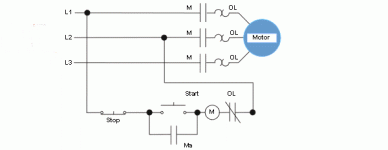
The attached picture might be of some assistance in helping you understand as to where the motor overload protection comes from.

The -|/|- OL contact will be used as an input to the PLC

Many thanks to Ron Doran for use of his picture.

Paul

stopstartmotor.gif
 
As Allen so correctly points out, don't get obsessed with the PLC programming software. The ladder logic to control this system won't be too many rungs, so you should be able to transcribe it from your notes to the PLC in the lab in a fairly short time. The exercise is to learn about programming in ladder logic, not about any specific programming software.

A point I neglected to make in my earlier post. If you do get a copy of the Windows programming software for the specific model of PLC in the lab, be aware that you'll probably be able to import a program file from the DOS version to the Windows version, but don't expect to be able to go in the opposite direction. So if you spend a lot of time working at home using Windows software, the files you create probably won't be readable by the DOS software that your school uses in the lab.
 
You certainly are seeing my true colours now. Must have used the scroll without clicking off when I set my profile, sorry for any misleading info.
Understand what you say about the software, should try harder with the dos progs just lazy I suppose. Will post my intial attempts with this exercise in a day or so, would grately appreciate any comments.Not looking here for answers only guidance
Thanks to all so far
 
Have been trying to sort this prob
PLC 405

// Rung 1
// Address 0
STR X0
SET C0

// Rung 2
// Address 2
STR C0
ANDN X2
OUT Y0

// Rung 3
// Address 5
STR C0
TMR T0 K200

// Rung 4
// Address 9
STRN X6
OR T1
AND C0
AND T0
AND X5
ANDN X2
ANDN X3
OUT Y1

// Rung 5
// Address 17
STR C0
AND X5
TMR T1 K100

// Rung 6
// Address 22
STRN X5
AND C0
AND T0
AND X6
ANDN X2
ANDN X4
OUT Y2

// Rung 7
// Address 29
NOP


#BEGIN ELEMENT_DOC
"X0","Start","",""
"X2","Fan O/L","",""
"X3","M/C1 O/L","",""
"X4","M/c2 O/L","",""
"X5","M/C1 Start","",""
"X6","M/C2","",""
"Y0","Fan Motor","",""
"Y1","M/C1","",""
"Y2","M/c 2","",""
"T0","20 sec Delay","",""
"T1","10 Sec Delay","",""

#END

Have been trying to ork on the sequence of poss op's. few more to go I think ?
TI 405
Softare version 2.1
any comments would be much appreciated.
 
I'm getting senile. Although I can read the STL, I can't follow it like I can ladder. So here's trawets' logic in ladder:


START "mcr"
X0 C0
---| |-----------------(SET)


"mcr" FAN O/L FAN
C0 X2 Y0
----| |--------|/|------( )


"mcr"
C0 T0
----| |---------------( TMR )
( K200 )


M2 START "mcr" M1 START FAN O/L M1 O/L M1
X6 C0 T0 X5 X2 X3 Y1
---|/|----+---| |---| |------| |------|/|------|/|-------( )
|
|
T1 |
---| |----+

"mcr" M1 START
C0 X5 T1
---| |------| |------( TMR )
( K100 )


M1 START "mcr" M2 START FAN O/L M1 O/L M2
X5 C0 T0 X6 X2 X4 Y2
-----|/|-------| |---| |------| |-------|/|------|/|------( )


There, that's better. Now I can SEE what's going on.

Many points to make:

1) You SET C0 (which I labelled "mcr" for "Master Control Relay" since you didn't have a label for it), but you never reset it. Therefore, by your logic, as long as the fan doesn't overload, it will never stop (short of cutting off the power to the PLC).

2) This goes back to the first thing I asked you to do, and you neglected. MAKE A COMPLETE I/O LIST. Your list of inputs is incomplete. You start things, but don't stop them. So you'll need an XI (Fan Stop), X7 and X8 for M/C STOP 1 & 2. Now is your list complete?

3) You have a requirement "(d) From the time that the last motor is turned off a 20 second delay is required before the exhaust fan may be stopped.". I don't see any sign of that in your fan logic (Hint: See point #1)

4) This is something that you probably wouldn't know: Motor Starter relays's have built-in overload protection. There ia an Auxillary Contact (which is electrically normally open) which gets used as a PLC input to let you know that the motor is running, not that the overload is OK. So that input will not be received by the PLC until AFTER the output is energised (or some sparky uses a screwdriver to push the relay closed manually). The AFTER is important. There is a mechanical, electrical, and logical delay before you know that the motor that the PLC tried to turn on didn't respond to the output request (the reason isn't always the overload - it could be bad wiring, a bad starter relay, a bad PLC output).

5) On your annotation, you call T0 and T1 "20 sec Delay" and "10 sec Delay". I can SEE that they are set up for 20 and 10 secs. But what is the DELAY about? WHY are you delaying? Better annotation for T0 might be "FAN On for > 20 sec" or "FAN ON; OK to Start Machine". That's the purpose of the timer. That kind of annotation makes it easier for a) you to follow what you are trying to do; and b) someone else (or even you, at a later date) follow what you were trying to do. And don't forget to label your internal coils (like C0). If you can't give it a clear comment of what it's supposed to do, then you don't understand what you are trying to accomplish clearly enough.

I appoligize if I've seemed harsh here. I don't mean to be. You've made a pretty good first attempt. But, as you indicate, there's still quite a bit of work ahead. Keep at it.

Good luck!
 

Similar Topics

I need to know how to take a schematic like this and solve it for let’s say a run time of 5 seconds By solve I mean determine which rungs are...
Replies
33
Views
9,094
Q(1) Design a controlling system using DVP-40ES Delta PLC for a threestory Elevator Prototype as shown in the figure below. Show in details the...
Replies
4
Views
2,147
Hello this is jitu. I am a new in this PLC Ladder coding. Anyone help me to write this problem. I am also try to solve this but not successfully...
Replies
12
Views
3,252
Hi, I'm new to PLC ladder diagrams and I'm stuck in a problem where I'm given a ladder diagram (please refer to the attached file "Problem"). I...
Replies
8
Views
7,518
Hi everyone. Long story short, we are using ladder logic to run an SFC. Due to the nature of an SFC we need about as many timers as we do states...
Replies
4
Views
5,299
Back
Top Bottom