Tuning a Slower Loop (AB CLX)

phuz

Member
Join Date
Jun 2008
Location
Mohnton, PA
Posts
1,044
System: steam cooker with a volume of about 900 cubic feet. 2" steam valve. RTD for temperature input.

From a cold start, valve wide open, it takes about 8 minutes to reach temp, but when it gets there, it holds pretty well. The issue I am having is when they introduce product, the temperature will dip, and per government regulation, we cannot drop more than 2 degrees. The valve is certainly able to keep up, but I am noticing the loop (PIDE) is not using as much output as it needs to.

The temperature is dropping about 1.8 degrees, which is dangerously low to the low cut-out. At steady state prior to introducing product, the CV is about 20%. When product is introduced, I only see the loop ramp up to about 35% all while the temp is continuing to dip. I started with PID parameters of 20 / 1.5 / 0 and even increased the PI to 35 / 2 but I am still not getting as big of a reaction as I would expect.

I have a couple other quick-acting loops that are almost perfect, but I am struggling with this slower one. I'd appreciate any insight from the PID experts.
 
You could use a feedforward when introducing product, so the PID output momentarily "jumps" up proportional to the added "energy demand" (cold product) and continues to control from the new "base point".
 
Last edited:
Yeah, that'd be nice, except we have no feedback when product is being introduced. It comes in on a conveyor with no inputs to our system. This system was originally controlled with old panel-mount loop controllers (think 1970s). It controlled OK on those, so I just need to get my tuning ironed out. In order to get a bigger response, I would have expected to just increase the Pgain, except it isn't doing what I want. Remember, I went from 20 to 35 with no real difference. Do I need to be more dramatic with it?
 
Yeah, the old "programmer has a crystal ball" problem..

Someone else has to answer about the specific PID in AB, because I don't know jack about AB plc:s.
 
I think that with AB PLCs running a PID function, the lower the number for I is, the less time it allows to pass before ramping up the output when an error is present . So to make it add more heat with less time elapsed during a temperature deviation, decrease the I term. You should also have the P as high as possible to the point where a steady state starts to go into oscillation, then back it off about 10-20%. For steam heating a vessel, this has worked well for me.
If the temp drops from say 100 down to 95, your CV should be opening up a lot more than what you are reporting. But balance it out by ensuring the CV drops as you get close to SP. And while you're at it, cook up some lunch for yourself.
 
Last edited:
Rate or Derivative, the D term in PID, will boost the gain based on the rate of change of the error. When a cold load is introduced to a stable environment, the temperature drops off which is a high rate of change compared to idle steady state which is a near zero rate of change).

Try a 0.5 factor in the rate term and watch how much the gain increases at the load change.
 
If the response from cold startup does not have too much overshoot (assuming initial heat-up is in Auto), then you have some working margin to make the P-I gains more "aggressive." For the proportional action, increasing the P gain will make it more responsive. For Integral, it depends on whether the dependent or independent controller type is selected (DependIndpend input). For Dependent, I units are minutes/repeat, so a smaller number gives you more integral action (i.e., repeating the P action more quickly). For Independent, I is a direct gain in units 1/minutes, meaning a larger number is more integral.

If you are using dependent gains, it is generally recommended for the I gain to be the first order time constant if the process behaves like a first order system. Let's say, for example, this is 5 minutes for the heating process described. Set Dependent I to 5, and then increase P until there is undesirable overshoot on the initial heat-up. This is presumes 5 is a reasonable estimate of the first order time constant, which can be determined by an open-loop step response.

With the Independent gains selection, you will need to work with both values to get the desired response, increasing P and/or I to get faster response without too much overshoot.
 
This may not helpful but most cookers I've run across use plain old on/off steam valves because of the tremendously slow response as you've mentioned. Sometimes with big valve/ little valve arrangement.

Is it possible to just do a 0.5* dead band and make it on/off?
 
I could verify easily implement on/off control, but the fact that we have a proportional valve and a very-capable controller, I'd hate to do that. I am determined to get this working. One thing I have been reading that has caught my interest is the introduction of noise into RTD signals. Currently, the RTD has a 50' run from the probe to the chart recorder, and then is converted to a 4-20mA output to the PLC. I have opted to change this out for a 4-20mA transmitter at the probe itself, and put the PLC and chart recorder in series so we have a more stable signal, and no reliance on the chart recorder's output for control. I am expecting improvement, even if minor.
 
Yeah, that'd be nice, except we have no feedback when product is being introduced.
:(

It comes in on a conveyor with no inputs to our system. This system was originally controlled with old panel-mount loop controllers (think 1970s).
If the guy that designed those 'old' panel-mount loop controller knew what hes was doing, it may be hard to match those 'old' panel-mount loop controller

"It controlled OK on those, so I just need to get my tuning ironed out. In order to get a bigger response, I would have expected to just increase the Pgain, except it isn't doing what I want. Remember, I went from 20 to 35 with no real difference. Do I need to be more dramatic with it?[/QUOTE]
Why bother to ask questions when you don't provide information to give an intelligent answer.
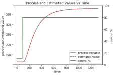
Lets see a trend at least with the SP, PV and CV shown.
Better yet, provide a .csv file with 3 columns of time, cv and pv.
I can run it through my auto tuner.

http://www.plctalk.net/qanda/attachment.php?attachmentid=50715&stc=1&d=1555001941
RMS error = 0.436
The open loop gain = 3.757 PV/%CO
Time constant 0 = 170.959
Time constant 1 = 41.073
Ambient PV = 77.839 in PV units
Dead time = 21.243
Time units are the same as provided in input file
The closed loop time constant = 17.096
The controller gain = 1.472 %CO/unit of error
The integrator time constant = 212.032
The derivative time constant = 33.116

The data came from Ron Beaufort's 'Hotrod' training units in 2005.

The data file looks like

Code:
"time"	"CO"	"PV"
0.00	10.00	114.00
1.00	10.00	114.00
2.00	10.00	114.00
3.00	10.00	114.00
4.00	10.00	114.00
5.00	10.00	114.00
6.00	10.00	114.00
7.00	10.00	114.00
8.00	10.00	114.00
9.00	10.00	114.00
10.00	10.00	114.00
11.00	10.00	114.00
12.00	10.00	114.00
13.00	10.00	114.00
14.00	10.00	114.00
15.00	10.00	114.00

hotrod.png
 
Last edited:
I could verify easily implement on/off control, but the fact that we have a proportional valve and a very-capable controller, I'd hate to do that. I am determined to get this working. One thing I have been reading that has caught my interest is the introduction of noise into RTD signals. Currently, the RTD has a 50' run from the probe to the chart recorder, and then is converted to a 4-20mA output to the PLC. I have opted to change this out for a 4-20mA transmitter at the probe itself, and put the PLC and chart recorder in series so we have a more stable signal, and no reliance on the chart recorder's output for control. I am expecting improvement, even if minor.

I'd be interested to see what happens. I work A LOT with RTDs and 4-20 loops and have always wondered which one is more susceptible to noise. But I think they are both equally susceptible...its the wiring that picks up noise and the receiving controller or conditioner is mostly what determines how well noise is filtered or tolerated. I don't buy into the notion that since RTDs provide a resistance value that probably gets converted to a voltage somewhere inside the receiving electronics, that they would be more susceptible...the 4-20 will also probably be ultimately read via some kind of voltage level inside the receiver so I think it all boils down to the quality of the noise filter (leaving aside talk of shielding and length of cable runs).
For some unknown reason a lot of machines I work with have the 4-20 sensor cables shielded and grounded and the RTDs cable left unshielded...but the cable runs are not that long......
 
Well the 4-20mA definitely seems more stable in terms...but I still had issues with the PID values we were using. I ultimately decided to scrap those and start from scratch with P, then add I to get desired results.

I ended up with P: 45 I: 115 D: 0
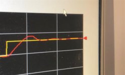
and have the follow graph when bumping the setpoint up 10 degrees.
I received a msg from the plant today that when they introduced product, the temperature only dipped 0.2 degrees (we're allowed 2.0 degrees for the process), so everyone is rather happy with it.

IMG_9451 (Small).jpg
 

Similar Topics

Is it possible for me to tuning 2 servo at the same time, because this servo is connected by mechanical so I'm afraid that I need to tuning them...
Replies
3
Views
136
Have a logix controller and I'm using the PIDE block for the autotuner. I've got the hang of doing it for direct control things like pressure...
Replies
21
Views
1,765
Hello all, I am using a PowerFlex 700 (Rev 10.001) to maintain tension in a web. We're reading lbs from load cells under one of the rolls...
Replies
85
Views
11,575
Hello, I am attempting to tune a PID loop on a process. The process involves a valve with electronic actuator that has quite a high deadband...
Replies
10
Views
2,181
Hi Guys, During PID Tuning by Ziegler Nichols Closed-loop method, In TIA Portal there is a Trend Tool used to determine Ultimate Period; marking...
Replies
9
Views
1,869
Back
Top Bottom