Deadtime on a digital signal

JLand

Member
Join Date
Apr 2019
Location
Madison, Wisconsin
Posts
114
Hi folks,

I have a situation where I need to read a digital input and output a digital signal based off of this input plus some delay.

For example, the input will go high for just 1 second. 20 seconds after it first went high, my output will go high for just 1 second.

The delay will be an HMI setpoint and the digital input may be on for any amount of time ( it could be more than or less than the delay) and the digital input may cycle on and off multiple times in the duration of the delay timer.

What's the best way to do this?

For reference, I am running on an AB L72.

Thanks!
 
Last edited:
Originally posted by JLand:

...the digital input may cycle on and off multiple times in the duration of the delay timer.

Are additional inputs during the delay time ignored or do they reset the delay? Are additional inputs supposed to be tracked and produce their own delayed output?

Keith
 
you could also hook the two together with 20 light-seconds of cable, but then the delay would not be adjustable from the HMI, so forget that.
 
You just need to break things down in to bite sized pieces.

1) What instruction would you use for timing the 20 seconds from the button being pressed to the output turning on?

2) What instruction would let you keep the output on for X amount of time and then turn the output off? I'll give you a hint on this one, because many people get this wrong. The TOF instruction is a tool of Satan and should never ever be used. People who say otherwise, likely hate the Packers, brats, and puppies. Don't be that person.

Sort those two issues out, and post the code you came up with. From there we can help get the rest of the issues sorted out.


Bubba.
 
The TOF instruction is a tool of Satan and should never ever be used. People who say otherwise, likely hate the Packers, brats, and puppies. Don't be that person.

Noooooo it's so handy, though! Poor old TOF instruction... it means well but is so misunderstood.
 
The TOF instruction is a tool of Satan

Hey Bubba, I dunno about the instruction, but the [Help] page for TOF is definitely in the satanic realm: I've read it about five times and still haven't the foggiest how the TOF works; I'll have to figure it out empirically.

Update: the first sentence of help says everything; the rest ties me in knots, but I think I got it now.

One side effect is that I am starting to hallucinate that it's analogous to a NAND logic gate, and would actually be more efficient to use, once it's understood.

A TOF Haiku

Misunderstood TOF:
Cannot tell if on or off;
Help dialogue won't;).
 
Last edited:
I don't think the TOF itself is difficult to understand, it is just difficult to understand why anyone would use it. The reason being is that ladder is a beautiful work of art, a simile if you will for real electrical relay circuits. You put power in one side and it flows through to the other side. So what then, pray tell is a TOF doing, where you kill power to it and it keeps on ticking? Ah, sure, in the real world you have a TOF timer relay. But really it has two inputs, a control power and a signal input. Kill power and it turns off. The Ladder TOF was an imitation of this relay, but a poor imitation. A Picasso if you will; sure it's art, but you put it in a museum with other such artwork that confront the viewer. The art you want for ladder does not confront, it gives the viewer a sense of order and control.

I am curious to read the help again for TOF, because as I said I don't think the instruction is that hard to understand. Maybe because I tested it all those years ago, as you say. I guess with Rockwell they call the output DONE, which is stupid, the timer's not DONE at all - it's output bit is on, either because the input is currently on, or it has been on sometime in the last x milliseconds.

And for the OP, use a FIFO. The OP requirement is you can press the button multiple times and repeat the pattern. Lare had it right, after only 28minutes. I am sure the homework assignment is complete by now.
 
I am curious to read the help again for TOF, because as I said I don't think the instruction is that hard to understand. Maybe because I tested it all those years ago, as you say. I guess with Rockwell they call the output DONE, which is stupid, the timer's not DONE at all - it's output bit is on, either because the input is currently on, or it has been on sometime in the last x milliseconds.

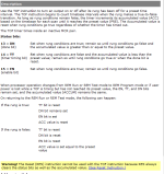
See below. I don't know what my problem is, but once the light bulb came on it gets clearer each time I read it. Boolean is simple to me in principle, but the number of times I get it wrong just blows me away.

So what then, pray tell is a TOF doing, where you kill power to it and it keeps on ticking? The reason being is that ladder is a beautiful work of art, a simile if you will for real electrical relay circuits....The art you want for ladder does not confront, it gives the viewer a sense of order and control.

I think that is it: ladder is a simile, or model, for real relay circuits (mostly), and so I don't memorize the details of each instruction, I instead grok how each instruction fits the simile; and because TOF does not quite fit, I can't grok it in my model of relay circuits.


Code:
Description

Use the TOF instruction to turn an output on or off after its rung has been
off for a preset time interval. The TOF instruction begins to count timebase 
intervals when the rung makes a true-to-false transition. As long as rung 
conditions remain false, the timer increments its accumulated value (ACC) 
based on the timebase for each scan until it reaches the preset value 
(PRE). The Accumulated value is reset when rung conditions go true 
regardless of whether the timer has timed out.

The TOF timer times inside an inactive MCR pair.

Status bits: 

13 = DN (done bit) 
Set when rung conditions are true; remain so until rung conditions go false 
and the accumulated value is greater than or equal to the preset value.
 
14 = TT (timer timing bit)
Set when rung conditions are false and the accumulated value is less than 
the preset value; remain so until rung conditions go true or when the done 
bit is reset.
 
15 = EN (enable bit)
Set when rung conditions are true; remain so until rung conditions go false.


When processor operation changes from REM Run or REM Test mode to 
REM Program mode or if user power is lost while a TOF is timing but has 
not reached its preset value, the EN, TT, and DN bits remain set, and the 
accumulated value (ACCUM) remains the same.

On returning to the REM Run or REM Test mode, the following can happen:

If the rung is true:
 TT bit is reset

DN bit remains set

EN bit is set

ACC value is reset
 
If the rung is false:
 TT bit is reset

DN bit is reset

EN bit is reset

ACC value is set equal to the preset value


Warning! The Reset (RES) instruction cannot be used with the TOF 
instruction because RES always clears the status bits as well as the 
accumulated value. (See Reset Instruction.)

tof_help.png
 
Last edited:

Similar Topics

I am trying to impliment some pH control logic on a wastewater treatment system. We are useing 93% sulfuric acid and 57% magnesium hydroxide as...
Replies
5
Views
3,017
I want to study the PIDAT instruction autotuning in Omron CJ1M PLC. For that I want to simulate a process with deadtime and first order lag...
Replies
0
Views
4,156
Question to anyone with ideas about my thoughts on upgrading a very vintage timer, which is being used to switch between 2 5hp domestic water...
Replies
14
Views
429
I have a PLC type PM856 from ABB with some I/O modules and I get an error from the Digital Inputs model type DI801. The unit status shows error...
Replies
0
Views
260
I am monitoring two BMXDDO3202K digital outputs for their behaviour, they are each for opening and closing, and so the on time affects how far the...
Replies
1
Views
277
Back
Top Bottom