Happy Holidays Folks!
I am working on a robot cell and as we are adding PLC control to the system, I have some questions about implementing an upgraded safety circuit.
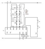
Currently (pre-PLC), the robot controller has 2 sets of safety inputs, an E-stop input and a “Protective Stop” input. There are two estop relays (Euchner ESM-BA301, datasheet here). The E-Stop pushbuttons are wired in series to one E-Stop relay, whose outputs (13,14;23,24) go into the robot E-Stop inputs. The light curtain output is OSSD and goes into the second relay, whose contacts (13,14;23,24) go into the “protective stop” inputs.
We want to re-wire this system with a Cat 4 setup using redundant contactors, such that both the light curtain and the E-Stop perform the same function (uncontrolled power cut of both robot and all actuators). The contactors would cut power to a few sets of designated terminal blocks powering PLC outputs, a couple servo motors, open the robot controller safety, etc. I’ve done this numerous times using a single relay with multiple E-stop buttons, but am not exactly sure how to wire both safety relays together to accomplish this, maintaining a Cat 4 system. A single reset button would need to reset one or the other relay, and there is NC contactor feedback from both the robot controller contactors as well as the planned redundant contactors (at safety relay outputs (14;24)) so I’m guessing the safety relays need to be cascaded somehow? Does anyone by chance have a schematic they would be willing to share showing how to do this?
As an aside, the way this system is currently set up has the light curtain safety relay auto-restarting on removal of the light curtain obstruction. Something about this doesn’t sit well with me; I don’t like the idea that there is no conscious re-powering of the actuators required. Is allowing auto-restart common practice for a light-curtain protected robot cell?
Thanks!


