OT - Capacitor reforming

Jim G.

Member
Join Date
Nov 2007
Location
Georgia
Posts
187
I came across some information concerning reforming of capacitors in VFD's that have been stored for more than 2 years. We have quite of few that fit that description.
Does anybody practice this as part of a periodic maintenance program?
Is there a ready made set up to perform this on a variety of drives?
Are there companies that will come into your plant and perform this service.
Thanks
 
The startup for old capacitors (memory here) was to power up the VFD at 50% (maybe 33%) the rated voltage for xx hours, then step up to 70% for xx hours, then 80% for xx hours, then full power for 1 hour.

The hours were from 4 to 8 hours per step. Starting at 8 hours I think, then dropping some each step. Of course, holding at the lower voltage longer wouldn't hurt the capacitors.

Maybe search Engineers Toolbox or Engineer On A Disk for exact specs
 
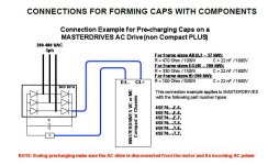
Attached is data from ABB about their reforming process. So maybe check the drive manufacturers website for their procedure.
 
I came across some information concerning reforming of capacitors in VFD's that have been stored for more than 2 years. We have quite of few that fit that description.
Does anybody practice this as part of a periodic maintenance program?
Is there a ready made set up to perform this on a variety of drives?
Are there companies that will come into your plant and perform this service.
Thanks

Yup. We have a PM where an electrician gets each of our spare VFDs off the warehouse racks, connects 2 terminals to a variac (R and S, I think), puts a meter on the DC bus, and raises the voltage in steps with delays between. The delays from step to step vary with the size (HP) of the VFD ... if I remember correctly.

When the electrician has to leave, the whole area is red-taped since there is exposed buss, conductors, etc.

We had a spare VFD pop one bus capacitor several years ago, when it was installed to replace a failed VFD. The capacitor failure did NOT shut down the VFD .. which was impressive .. but it would not run at rated output. We limped through a weekend before another replacement was flown in.

The Spare had been on the shelf for about 5 years, and had never been powered up. We don't know if it was a reforming problem or there was just a defect from the factory.

We have changed brands and models since that failure. But we have not had a capacitor failure on a spare since that one.
 
Jim > Does anybody practice this as part of a periodic maintenance program?


We used to have a guy who was supposed to do that to our spare Siemens Drives
once a year. . . . he left us and then our company downsized . . . if I have to replace
one first thing I'll be doing is re-forming the capacitors before installing.

Below should be part of a page from a Siemens document with a schematic
very similar to what we are using.
Poet.

http://www.plctalk.net/qanda/attachment.php?attachmentid=50673&stc=1&d=1554401715ng

Siemens_reform.JPG
 
Bonitron makes a nicely packaged Capacitor Reformer in a wheeled case. Not cheap, but I've built my own with a variac and it's not easy, nor is a variac cheap unless you find one on Craigslist or Fleabay and finding one capable of the voltage you need for a 480V VFD is damned near impossible.


http://www.bonitron.com/m3628pcf.html

We use a 3 KVA variac fed with 120 VAC, then the output of the variac goes through a 1 KVA control transformer (in the 120 VAC 'output' side, and 575 VAC comes out the 'supply' side)

The Variac is mounted to a 2 wheeler, above a hoffman enclosure with the transformer mounted inside, a switch and an indicator light for the 120V, and pigtails on the 575 VAC side. It's not pretty, but it works.
So you are feeding the drive with low voltage AC then? The problem with that is that you must then disconnect the control power supply for the drive internally, otherwise you are feeding low voltage to the PC boards and stressing them and if the VFD has been sitting idle for 2 years, they are old too. Not all VFD designs allow you to do that. The proper way to reform the caps is with DC after disconnecting them from the bus. I fed my variac into a rectifier and smoothing caps (which is what the Bonitron unit does), but on a 480 or 600V drive, the DC output wires are going to be over 600V, requiring special insulation. I found it all too cumbersome, that's why I bought the Bonitron after my homemade one was stolen out of my car (and likely ended up in a trash can when the Junkie couldn't sell it).
 
So you are feeding the drive with low voltage AC then?

The 120V goes into the variac. The output of the variac is 0 - 120VAC. And that 'backfeeds' the control transformer. Normally the control transformer steps 575VAC single phase to 120VAC single phase.

But 20V into the output terminals gives about 90VAC out the high side of the transformer. Adjust the variac to get the DC bus voltage (after the diode bridge and the pre-charge resistor)you want. The capacitors that are being reformed are doing the filtering ... likely not ideal. But that's how we are told that our supplier does the VFDs that they have on their shelves (older stock).

As for the boards, the DC/DC converter that supplies the power to the electronics does not appear to function below 500V. Above 500VDC on the bus the electronics power up and give various warnings about Emergency Stop terminals not driven, low bus voltage, etc. Perhaps the power supply is actually AC to DC, as we must use R and S for the input. Using R and T or S and T works for charging up the DC bus, but never powers up the control boards.

Perhaps we are stressing the boards somehow.

I guess this is not a good general-purpose description. As you say, not all VFDs will work with this setup.

In my experience, the manufacturer goes a bit over-board with the safety pre-cautions and procedures, for everything in general. Reforming caps, Preventive maintenance checks, air-filter changes, etc. Your distrubutor/supplier/reseller .. whoever sold it to you .. may be a resource for a more practical method.
 

Similar Topics

Hey guys, I know this is not PLC related but many of you are pretty crafty. I need to resurrect an old PowerFlex 700 VFD. AB calls for reform...
Replies
4
Views
2,327
One of my colleagues came across this note from ABB indicating that VFD's not in service for more than a year or two, depending on circumstances...
Replies
3
Views
6,017
Hello Everyone, In need of some most needed help on troubleshooting a Kinetix 6000 servo. The first one smoked and was replaced only to smoke...
Replies
1
Views
1,276
Hi all, there is something that is not making sense to me. Upon system powerup, twice in a row two brand new Sinamics PM240-2 started smoking and...
Replies
3
Views
1,594
Somewhat off topic but wondered if anyone could give me a place to start. Last year a customer wanted a very rough and ready and cheap speed...
Replies
10
Views
2,511
Back
Top Bottom