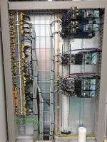
Motor terminals

Anything less then 250HP here must go through either terminals, or a power block mounted in line with the terminals. Direct connections to any device are frowned upon.
Objectively - why ?

IMO there is no question about it for drives, the motor cables should be connected directly on the drive OR the output filter for the drive, and the screen should be terminated as close to the drive as possible. If the cable goes directly on the drive, there will be a clamp on the drive itself to terminate the screen.
We always follow the manufacturers recommendations (because that makes it easier for us to state that the panel is made for a certain EMC environment), and this is always what the manufacturers recommend.

Even for normal motor-starters without drives, we connect the motor cables directly on the motor starter itself.
I see no downside to doing it so, only advantages.
Here is a photo from one of our recent control cabinets. The motor starters are in the right side of the cabinet.

panel_with_driect_motor_starter_cables.png
 
Let me first start out with this
A standard I have set for myself for new panels is this,
As I have said this is just a standard I use for myself, I find it works very well and makes things simple for even an inexperienced electrician get the connections right and later it makes it much easier to trouble shoot.
As I am always trying to improve my work I would welcome any and all suggestions you may have to offer to that end.

Everything entering or leaving a panel, where practical is terminated on a terminal block in close proximity to where the wire enters the panel. The exception there would be a power feed over 100 amps would go directly to the disconnect or very large drives then they should be mounted in a way that allows the field installer to access the terminals without accessing the wires in the panel.
Never ever allow the field installer to access anything beyond the above mentioned terminal blocks, there is just no end to the problems that can create.
Group my terminals together
Power in as a group, motor leads exiting the panel as a group with sub groups per motor with a ground terminal per motor group. Control power out as a group Low voltage power out as a group, sensors / switches in as a group, encoders as a group again with sub groups for each encoder. And then a group for any safety devices external to the panel with a sub groups for monitored and unmonitored circuits each major group separate with a minimum of 2 unused terminals
In addition to the above grouping I also like to use different colors for different type of circuits. Power can be black or standard gray, 120V and above sensors / switches gray, 24 v power and sensors are blue the monitored safety circuits are red unmonitored safety circuits are blue
Leave plenty of extra room for the field wiring to enter the and be terminated.
Another standard is specifying that no holes may be punched in the top of any panel unless a properly installed weather hub is used. I have seen too many times where leak in a pipe or condensation or liquids drip into a panel and cause many problems let’s try and stop the problems before the happen.
I have even taken the extra step and have a local metal show fabricate angled mounting brackets for the DIN rail on the external terminals.

As a note if you are using the DIN rail as a grounding connection ( grounding terminal blocks) you may not use aluminum rail and you must bond it to the panel and the panel ground connection using a separate indentified grounding screw ( Not a mounting screw). Aluminum din rail is not rated for grounding, I think it has to do with aluminum to steel connection is a very poor electrical connection.

One final thing I see that some are concerned that using a terminal block will not have a higher than 10K current interrupt rating. That’s strange because that rating is the maximum fault current interruption rating for the fuse or breaker protecting the panel or device a terminal is not an interrupting device no more than a buss bar or wire is so I would not see how that would have any effect on that rating.
 
Never ever allow the field installer to access anything beyond the above mentioned terminal blocks, there is just no end to the problems that can create.
As you can see in the photo of our panels, the field installer connects to the motor starters in exactly the same way as if he should conect to terminals.

In addition to the above grouping I also like to use different colors for different type of circuits. Power can be black or standard gray, 120V and above sensors / switches gray, 24 v power and sensors are blue the monitored safety circuits are red unmonitored safety circuits are blue
You defined your own wiring color standard ? Hmm.....

I have even taken the extra step and have a local metal show fabricate angled mounting brackets for the DIN rail on the external terminals.
You can buy those angled brackets. I take that you are using screw terminals. Back in the days before we changed to cage-clamp terminals we also mounted the terminals on an angled DIN rail.
With cage-clamp terminals there is no need, since you insert the wires from the top.

One final thing I see that some are concerned that using a terminal block will not have a higher than 10K current interrupt rating. That’s strange because that rating is the maximum fault current interruption rating for the fuse or breaker protecting the panel or device a terminal is not an interrupting device no more than a buss bar or wire is so I would not see how that would have any effect on that rating.
All devices in a cabinet that conduct current and also the cabinet itself must be rated for the SCCR current it may be exposed to. "passive" components must not break from the magnetically inudced forces that are caused by the short circuit current. A manually operated switch must be possible toopen even after it has been exposed to the SCCR current.
 

Similar Topics

Hello, It is mandatory to use VFD IF i use IE5 electrical motor? What happens If connect it directly as delta without VFD? Please look at motor...
Replies
1
Views
127
Here's what happened, Operator turned on the disconnect for an auger while it was still running to cut power. Auger DID in fact turn off, but the...
Replies
8
Views
331
Hello all, In my facility we have multiple 3HP 460V motors that are being controlled by VFDs which drive conveyor belts. The drives are randomly...
Replies
2
Views
200
Hi everyone, This is my first time posting, so please forgive any omissions or mistakes. I am attempting to control the velocity of a stepper...
Replies
18
Views
983
Kindly, has anyone tried to control Lenze servomotors with Siemens S120 drives ? Any special hints ? Have some concerns for the resolver and servo...
Replies
5
Views
228
Back
Top Bottom