Plc inputs/outputs wiring

renatusigm

Member
Join Date
Feb 2012
Location
Dar-es-Salaam
Posts
9
Hello guys, I am Renatus. This is my first time to join and participate in this forum. I am a student and am pursuing my project for additional overheating protection of Induction motor using PLC. The system will incorporate the proximity sensor which will be used to detect the rotational motion of the motor, the signal (voltage pulses) from the proximity sensor will be the input to the PLC and that signal I will be programmed such that the Timer On Delay will be activate to switch the power supply Off when the signal into the PLC is not detected within the 30sec when the motor stalls (Blocked by external matters) or running at low speed. I have planned to use Micrologix 1000 PLC.

My difficult is How will I make the wiring of the PLC inputs with start,stop push button and proximity sensor and the output of the PLC with the motor starter?
please guys I really need your help on how to do wiring in PLC because I am still a beginner in PLC field. thank you.
 
I would certainly NOT be looking at a pulse to stop a stalled motor, you will almost certainly burn it out. Either use a motor circuit breaker to protect the motor (really7 simple and an auxiliary into the PLC) or a mcurrent transducer into ,an analogue card to read the current, or both.
 
No, he is using the pulse as a speed detector. When zero (or very low) speed is detected when the motor should be turning then his circuit will kill power to the motor to protect it.

On our machines certain actions are triggered as a result of encoder feedback from the drive mechanism. As a secondary effect we check for zero or very low speed and generate a fault if the system should be freely moving.
 
The motor is being protected by the circuit breaker, fuses, and Variable Speed Drive (VSD) all of these three will check if the current is 1.25 time the rating current of the motor the Power should be turned off. Thermistors in motor winding are not effectively they operate perfect when new but as the times goes they are failing to open the circuit to turn of the Power supply when the temperature raises above the allowable limit. When the motor stalls at it nominal speed the VSD will turn off the Power, But at low speed also the current is low the VSD, CB are not able to turn OFF the Power supply. That is why am adding this new system to assist those mentioned to turn Off the Power when the Motor Stall at low speed.

I need you view and any suggestions to accomplish my project.
Should I upload the flowchart of my design to elaborate how the system will operate so that you may advice me if there is anything necessary missing?
 
renatusigm,

I've attached something that may help shed some light on what I think your after. Hopefully this will be of some help. Good Luck
 
Ddnnis,

Good intentions, but 1 timer just will not do the whole job. Having used this method many times, it becomes apparent that the motor can stall with the prox in TWO different states. If your logic does not look for a time-out on EACH state, then the motor can stall (in your case) with the prox "closed" (target at rest under proximity switch). with timer disabled and never timing out.

Solution: use two timers, one for Prox ON time, the second for Prox OFF Time.
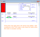
One timer can work, but you are right that both states need to be monitored. With one timer and two reset rungs it can be done:

stall_fault.png
 
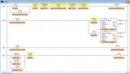
ddnnis, Lancie1, OkiePC and bernie_carlton thank you all for your helpful Ideas and knowledge. I have set down and take your Ideas and I have come up with this design you can check out to see if I am in the right truck.

When the start I:1/0 activated the coil O:2/0 will be energized and the motor starter will turn on the motor.
the two timers T4:0 and T4:1 will be set and reset when the proximity sensor signal (pulse) in either of those two states; on the target or off the target respectively.
when either of those timers won't be reset within 30sec the DONE signals from either T4:0 or T4:1 will turn off the power and Indication of fault will be displayed at the panel.

Please check out to see if my additional Ideas worked out. Thank you Guys.
Note: see the DESIGN OVERVIEW attachment.

DESIGN OVERVIEW.jpg
 
Renatusigm,

Your program appears to work as it is. However, check these items for possible improvements:

1. If your Stop pushbutton is a traditional "normally-closed, maintained-contact" switch, then for Rung 000, you need to change the Stop XIO (Examine If Open) to a XIC.

2. In Rung 000, you have used the "belt-and-suspenders" approach to de-energize O:2/0 if the prox switch timers reach DONE. You have both Timer DN bits AND your MOTOR STALL bit to cut off the motor contactor. You really only need one or the other, not both.

Using two things to do 1 job adds to your program complexity, but does not add any benefits. I would remove the Timer DN bits from Rung 000.

3. Do you really want to wait 30 seconds to determine if the motor has stalled? Consider the minimum speed in motor Revolutions per Minute. If it is more than 2 RPM (1 revolution every 30 seconds), then you can reduce the timer Presets so that they are slightly more than the time for 1 motor revolution at the minimum operating speed. This will give you much faster motor stall detection. (This assumes that your prox switches are looking at the motor shaft and not a gearbox output shaft). For example, if your motor is 1800 RPM at full-speed, then a likely VFD minimum speed would be 10% of 1800, or 180 RPM. 180/60 = 3 revolutions per second. Therefore, you could reduce your timer Preset values to only 0.333 seconds.

Most likely you are monitioring a slower gearbox or belt-reduced shaft speed, so set your timers accordingly.

4. One more thing about your proximity switch ON and OFF timers: The ON timer really does not need to be set as high as the OFF timer. The prox target is probably a narrow strip of metal, so the ON time will be short (whatever the time it takes for the target to pass the switch at the minimum motor speed), where the OFF time wil be close to the minimum shaft revolution time. Reducing the ON timer to some lower value will result in better stall detection. This is one good reason to use TWO timers instead of one.
 
Last edited:
If you use a pulsed input or one shot rising input from the prox switch , you can use one timer.

I would count the pulses and every 2 or 3 seconds clear the counter

If current count is greater than previous count then current count equals previous count.

Once the current count get up to speed, then start looking at the pulses.

Then latch a run bit once the start up phase has passed . Could be a number of pulses or a number of pulses per time period.

You don't want to alarm during start up.


As long as you use a one shot, you don't need to use an on time and an off time.

Pulse input to one shot
count pulses
every X seconds move counter value to a memory register, A ,and clear count

If A is greater than B, move A to B <max speed is captured, reset value when motor is commanded to run.

If A is less than some number, you have a stall

If A is less than some amount of B then the motor is slowing down

You could also capture the decreasing value and track the direction of the speed changes. Maybe the motor is just oscilating around some point, maybe it is slowly loosing speed over time.

I would also add A+C each time I cleared A to track total pulse count. This is how I know the motor has been running for some time so I don't alarm during start up. When C is greater than some number begin monitoring of speed.

Once C is greater than some value, then latch the "running" or "start up done" bit

As long as you write the value of the count to some memory location before you clear it, you can use that value as a direct speed reference if it is updated often enough.

There are usually enough counts per second to display a value that humans will perceive as "continuous"
 
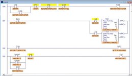
Thank you Lancie1, I didn't noticed some small mistakes I made. For what you have listed there your very true and correct as follows:-

1. My stop pushbutton will be traditionally "Normal Open" switch that is why I have used XIO (Examine If Open) in Rung 000.

2. In Rung 000 it is true I have used both Timer DN bits AND my MOTOR STALL bit to cut off the motor contactor. I really only need one or the other, not both as you have said and I have preferred to use MOTOR STALL bit only.

3. I don't want to wait 30 seconds to determine if the motor has stalled, but I was thinking on how to get the minimum time for safe stall and you opened my mind thanks for that. The Motor is 1420 RPM at full-speed and VFD minimum speed for this motor is 180RPM as well. I do agree with you in this 180/60=3 rev/sec. Your very right, I will reduce my timer preset to 0.333seconds (1/3 seconds).

4. When the proximity switch ON and OFF timer: It is true the ON timer should be very small compared to that of OFF timer due the narrow strip of the metal target.

I thought to use the same time for stall detection on both; ON timer and OFF timer for the consideration that if the motor stalls when the ON timer is on the metal target (narrow strip). Is that making any sense? or what do you think?

also see the program improvement on the attachment.

program improvement.jpg
 
I thought to use the same time for stall detection on both; ON timer and OFF timer for the consideration that if the motor stalls when the ON timer is on the metal target (narrow strip). Is that making any sense? or what do you think?

also see the program improvement on the attachment.
I like your method - simple and easy to understand, unlike some other methods.

For the ON timer, you really only need the longest time that the prox sees the metal target, but for purposes of getting the motor started (during which the speed will go from 0 to the Minimum Speed setting) you need both times to be long enough to allow successful motor start-up. Therefore, 3.3 seconds (33 X 0.1 Time Base as you are now using) may be about right. If you need faster stall detection, you would need to use an additional "Start-up Timer" that disables the Motor Stall output until the motor has time to reach running speed.

But at low speed also the current is low the VSD, CB are not able to turn OFF the Power supply. That is why am adding this new system to assist those mentioned to turn Off the Power when the Motor Stall at low speed.
It sounds like your requirements include detecting a motor stall during start-up also, so for that reason you probably do not want to disable the Motor Stall output during start-up. Therefore, you just need to determine, by running tests, what is the minimum times that you can safely set the timers but stilll allow normal starts from 0 speed.
 
Last edited:

Similar Topics

Can anyone check my answers on Input and Output of PLC Inputs Proximity Switch Switch Micro switch Thermocouple Voltage Sensor - Not confident...
Replies
7
Views
2,147
Someone please tell me so that I can die with a satisfied mind. Why, oh why, Do Beginners Think PLC Inputs Are More Important Than PLC Outputs...
Replies
82
Views
37,940
The PLC having a analog inputs/outputs to control the machine.... Analog inputs/outputs means a sinusoidal signals take to the PLC. but PLC don't...
Replies
2
Views
4,611
Gday, I'm having trouble with the analog input of my PLC (S7-314IFM). I am currently trying to run a DC VSD using voltage following...
Replies
2
Views
4,735
Hello, im a new student of PLC's and i wanted to know how u could connect npn and pnp sensors to a plc ... and also how to connect output to plcs...
Replies
8
Views
4,601
Back
Top Bottom