Factorytalk ME

Rehu09

Member
Join Date
Nov 2017
Location
USA
Posts
64
Hey all
I have created a application in ft me edition with rslogix 500 program offline tags.
I basically imported .eas file. All the tags with symbols, address got imported and created all the screens and used this tags in connection the components. Then created a shortcut with dummy Ethernet address as 10.1.2.34 in communication setup. So I used all the tags as direct referencing. After all the screens are done.
I went to some other PLC where another program is running right now the address of this PLC is 10.2.3.45
I want to test my application by connecting to the second plc. So what I have done I created a new communication path going to communication setup
Clicked on Ethernet selected 10.2.3.45 clicked ok.
Started test application as soon it started I find weird things in diagnosis banner one information show ur tag is incorrect, on information unable to connect 10.1.2.34. I don’t understand how to work now can any body suggest me
N
 
I'm not sure I understand the problem... so let me just outline a few things to check that are commonly overlooked.

If the tags are addressed directly to the PLC in the HMI program, they will look something like: ::[PLC]B3:0/0. If this is the case, make sure that the shortcut name you assigned to the second PLC connection in the communication setup is the same as the shortcut name in the tag's addresses. This is the text inside the brackets, "PLC" in my example.

If the tags simply have tag name, then you need to browse the tag database and look in the tag information to see what the connection address is. Again, verify that the shortcut name in this address matches with the shortcut name you assigned to the PLC you want to connect with. If you have an object on your HMI screen that is addressed to ::[PLC1]B13:10/0, you need to make sure that the PLC you are trying to use to test the program HAS a B13:10/0 in its program. If those addresses don't actually exist on the PLC, your HMI program is going to return a communications error.

Also, make sure after you set up your connections, you click the "Copy to runtime" option in the communication setup, in the top right corner of the screen. The tested application won't use the communication setup unless you do this.

If all of these steps are done and you still don't have connection, make sure that you can ping all the devices from your station to verify that they can communicate with each other. I see that your IP addresses have different values for their third sub group, is there a router that will make sure they are communicating with each other? Networking is my shortcoming in this world, but I do know that devices with different values in the first three groups of the IP address don't usually communicate with each other unless there is something routing those messages.

If none of this is helpful, try to elaborate on your issue a bit more to help me understand, because like I said I'm having a hard time making sense out of the OP.
 
Last edited:
I'm not sure I understand the problem... so let me just outline a few things to check that are commonly overlooked.

If the tags are addressed directly to the PLC in the HMI program, they will look something like: ::[PLC]B3:0/0. If this is the case, make sure that the shortcut name you assigned to the second PLC connection in the communication setup is the same as the shortcut name in the tag's addresses. This is the text inside the brackets, "PLC" in my example.

If the tags simply have tag name, then you need to browse the tag database and look in the tag information to see what the connection address is. Again, verify that the shortcut name in this address matches with the shortcut name you assigned to the PLC you want to connect with. If you have an object on your HMI screen that is addressed to ::[PLC1]B13:10/0, you need to make sure that the PLC you are trying to use to test the program HAS a B13:10/0 in its program. If those addresses don't actually exist on the PLC, your HMI program is going to return a communications error.

Also, make sure after you set up your connections, you click the "Copy to runtime" option in the communication setup, in the top right corner of the screen. The tested application won't use the communication setup unless you do this.

If all of these steps are done and you still don't have connection, make sure that you can ping all the devices from your station to verify that they can communicate with each other. I see that your IP addresses have different values for their third sub group, is there a router that will make sure they are communicating with each other? Networking is my shortcoming in this world, but I do know that devices with different values in the first three groups of the IP address don't usually communicate with each other unless there is something routing those messages.

If none of this is helpful, try to elaborate on your issue a bit more to help me understand, because like I said I'm having a hard time making sense out of the OP.
Thank you Logan,
You had covered almost everything what I was looking.
 
I'm not sure I understand the problem... so let me just outline a few things to check that are commonly overlooked.

If the tags are addressed directly to the PLC in the HMI program, they will look something like: ::[PLC]B3:0/0. If this is the case, make sure that the shortcut name you assigned to the second PLC connection in the communication setup is the same as the shortcut name in the tag's addresses. This is the text inside the brackets, "PLC" in my example.

If the tags simply have tag name, then you need to browse the tag database and look in the tag information to see what the connection address is. Again, verify that the shortcut name in this address matches with the shortcut name you assigned to the PLC you want to connect with. If you have an object on your HMI screen that is addressed to ::[PLC1]B13:10/0, you need to make sure that the PLC you are trying to use to test the program HAS a B13:10/0 in its program. If those addresses don't actually exist on the PLC, your HMI program is going to return a communications error.

Also, make sure after you set up your connections, you click the "Copy to runtime" option in the communication setup, in the top right corner of the screen. The tested application won't use the communication setup unless you do this.

If all of these steps are done and you still don't have connection, make sure that you can ping all the devices from your station to verify that they can communicate with each other. I see that your IP addresses have different values for their third sub group, is there a router that will make sure they are communicating with each other? Networking is my shortcoming in this world, but I do know that devices with different values in the first three groups of the IP address don't usually communicate with each other unless there is something routing those messages.

If none of this is helpful, try to elaborate on your issue a bit more to help me understand, because like I said I'm having a hard time making sense out of the OP.
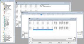
I have created all the screens everything is working good Thank you logan. But in few of the screen were showing error during runtime, went and dig out what was the cause. In every screen error was one common thing was used like I:3/31 or I:6/20 in indication.

Im surprised to see Why this application is not giving error for input bits 0 to 15bits like I:2/7. Why its throwing an error from 16bit to 31bit. The error during run time is like "tag has an error at ::[shortcut]I:3/31.
 
It has been a while since I worked with RSLogix 500 but you need to check how your data files look like and address accordingly.


Your input card may be displaying that there is 32 bits but maybe you can only use 15 it depends on your hardware presumably.

3.jpg
 
I:3/31 and I:3.1/15 should be interchangeable as far as the HMI software or the PLC software is concerned. I know for sure that RSLogix500 will accept either, and I'm 99% sure ViewME will as well, but you can try to alter the address to see.

The best way to make sure your object connection addresses are formatted correctly is to click the "..." to the right of the address entry field in the connections tab of the object (in ViewME) and browse to the PLC instead of typing them in manually. You'll have to drill into the folder name for your PLC and look in the "online" folder. You need to be connected to the PLC through the network to do this. If you don't see the "online" folder, right click on the PLC folder name and refresh it.

You'll only be able to find data tables that can be communicated with in there. If you can't find a particular tag address or data table, then that tag or data table doesn't exist in the PLC.

Caveat: You can't browse to the bit level through ME, so you'll have to find "I:3.1" and double click it, which will write it into the entry field. Then just manually type the "/15" at the end.
 

Similar Topics

how to communicate FactoryTalk Optix and Mitsubishi Q Series. I want to know the details of that
Replies
0
Views
36
Hoping someone can give me some guidance or confirmation of what I need to do. We have a FactoryTalk SE program that I need to change the IP...
Replies
2
Views
77
We are a water/wastewater plant, collecting realtime and manually entered data. We have been using FactoryTalk Historian (OSI PI) for real time...
Replies
3
Views
116
Good morning! Let me start by saying, I am still learning about this type of HMI programming. I recently watched a video about recipes and how it...
Replies
0
Views
68
Hello, I'm using FactoryTalk View ME V10. I created a valve as a global object with multiple parameters and when the object is being used at the...
Replies
2
Views
129
Back
Top Bottom