Allen Bradley BSL Instruction

Join Date
Apr 2002
Location
Burlington, Ontario
Posts
186
Hi all,

Ive got a situation where I'm trying to sequence through the bits in a word, actually, only the first 5 bits,once bit 5 is true, reset to bit zero and repeat. So it would look like this:


________________________________________
Word B3:10 |Bit | 0 | 1 | 2 | 3 | 4 | 5 | 6 | etc-> |
------------------------------------------
Shift 1: 1 0 0 0 0 0 0
Shift 2: 0 1 0 0 0 0 0
Shift 3: 0 0 1 0 0 0 0
Shift 4: 0 0 0 1 0 0 0
Shift 5: 0 0 0 0 1 0 0
Shift 6: 0 0 0 0 0 1 0
Shift 7: 1 0 0 0 0 0 0
Shift 8: 0 1 0 0 0 0 0
Shift 9: 0 0 1 0 0 0 0
Shift 10: 0 0 0 1 0 0 0


Im triggering the BSL on a 1 mS timer. Im having a hell of a time understanding how it works, and how to make it do what I want. Here's an example of what I've done so far:


T4:0/DN ----BSL----------------------
-----| |-----------------------| Bit Shift Left |-(EN)
| |
|File : #B3:10 |-(DN)
|Control : R6:0 |
|Bit Address: B3:11/0 |
|Length: 5 |
-----------------------------


Now, If I understand the instruction manual corecctly, Does the "Bit Address" insert a 1 into postion 0 of B3:10?? I was expecting that when I set B3:11/0 it would do just that, but it didnt. I'm very confused, If anyone could shed some light on how to use this instruction, or any other way of accomplishing this, I would greatly appricaite it. I guess I could use a sequencer, but that seems like too much work to just shift bits...Am I making this too complicated???

Thanks,

Andrew Evenson
 
I did a quick trial on a Controllogix. Make sure you fire B3:11/0 every 6th T4:0.DN. I am not very sure how the "length" works. It seems to shift bits through the whole word, even if the length is set to 5.

Does your BSL even seem like it's shifting at all? Put a couple ones in the B3:10 word and see.
 
BSL

The lenght refers to lenght of words (i.e. 1 = 16 ) , I think.

I usually use an ONS just before the instruction.

So if a cam makes a signal at say I:1/1 this drives a ONS.
the ONS goes to a BSL with File #B3:0, control R6:0 bit address of
say I:1/2 and lenght of 1.

So when the Cam goes High (at I:1/1 ) if the carton detect sensor
at address I:1/2 is high a "1" is move into the word B3:0 at whatever
position the control word R6:0 is at.

good luck
 
The lenght refers to lenght of words (i.e. 1 = 16 ) , I think.
Per the help file, the length is the number of bits shifted. BUT if you specify less than a full word of bits, the rest of the bits in the word cannot be used by other instructions as they will be shifted anyway. I think the length is used mostly to control when the UnLoad bit in the control word gets set.

Im triggering the BSL on a 1 mS timer.
For testing purposes, trigger this thing on a 2 or 3 second timer so your brain has time to process what it sees.

In your example data table, you're shifting a total of 6 bits (0 through 5) so your length in your instruction should be 6. If you want the thing to loop continuously, you would set the Bit Address to the UnLoad bit of the control word R6:0/UL. Before you start you would then have to make sure there is one and only one bit in the area you want to shift.

Another quick and dirty way to do a BSL without the control register is to multiply the word by 2. Then you have to do your own seeding of the data area. Document this so that when others look at it they can follow along.

After all is working, you can set your timer back to 1ms where it will be cycling too fast for you so see. ;)
 
I may be misunderstanding what you are attempting to do, but if your are just trying to circulate the bits as shown in your diagram then feed bit 6 into the bit zero position of the word by setting the BSL's Bit Address: to B3:10/6.

You will need to initialize word B3:10 to a value of 1 either manually or on the first scan.

No need for an OSN, as the BSL is a one shot operation like a counter.
 
does this help ... or hurt?

Andrew,

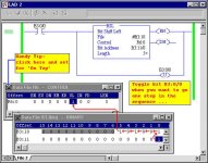
The red arrows in the screen shot below demonstrate what the program in your original post does when it executes “one step” in the sequence. Also - I’d recommend that you replace your “1 ms” (man, that’s really fast) timer with the “toggle the bit for one step” arrangement until you get the sequence running right. That way you can slow things down and see what’s happening along the way.

[attachment]

The manual does a pretty good job of explaining the BSL instruction. You might want to start reading on page 7-4 (Adobe Reader page 132 of 582) ...

http://www.ab.com/manuals/cp/1747-rm001c-en-p.pdf

I just threw in the hint about the “On Top” display feature for good measure - it makes it a lot easier to debug something like this. At least the display windows won’t keep playing “hide-and-seek” while you’re clicking on the screen to toggle the bits, etc.

Incidentally, the rest of the bits in the word (shown grayed out) are useless garbage. Don’t try to recycle them for any other purpose.

Good luck,

bsl.jpg
 
... more ...

And to answer your specific question:

Does the "Bit Address" insert a 1 into postion 0 of B3:10??

The answer is “only if B3:11/0 has the value of 1”. In other words, think of B3:11/0 (the “Bit Address” you entered into the BSL instruction) as the “loading zone”. When the BSL executes, all of the bits in B3:10 (the “File” you entered into the BSL instruction) move to the left one step (as I showed with the red arrows). And actually ALL of the bits in B3:10 (not just the first five) shift left - but we don’t really care about the extras. After the bits are shifted, the highest bit (B3:10/5 since you entered a length of 5 for the BSL instruction) is moved into the “unloading zone” at R6:0/UL. Then the BSL moves the value (whether it's a 1 or a 0) of B3:11/0 from the “loading zone” into the beginning of the bit lineup.

Finally, just what are you trying to do with this thing? If all you want is a rapid “ripple effect” of bits in sequence, then there are easier ways to do it than with this BSL instruction.
 
Why I'm looking to do this..

hi all,

I thank you very much for your help, comments, and suggestions. I've got to sit down and digest the information and test it out. I will let you know what my outsome is.

Ron:

I am trying to sequence Block Transfers. As you can see in my previous POST , I am having Analog Card Cards. Two in peticular "Lock Up", more specifically, the Block transfer instruction stops excecuting. The only way I can start the BTR again is to cycle the power on the PLC. Now, I have my local AB rep/tech support helping me with this matter, as well as AB's support group. My rep has suggested, I try to "Stagger" the BTR's, in thinking that maybe the local block transfer buffer/quere is getting full. He wants me to try this as it was a suggestion from AB themselves. If this doesnt work, we are going to look at hardware next. According to the programming examples in the AB PLC5 instruction manual, the BTR's can be triggered at any time. So, why not try. I only have to cycle through 5 analog cards. The 1mS timer is to allow my to request data from all cards within 1 second. The 1 second comes into play because all the PID loops are excectued on a 1 second cycle timer, so that gives me lots of time to update the input data in between PID excecutions. So, I hope my long winded explination helps.

PS: I'm game for any other suggestions..

Thank you,

Andrew Evenson
 
... and more ...

Actually, now that I’ve had time (in between customer calls) to take a good look at your first post, you WERE quite specific about how you wanted this thing to function. This should satisfy your requirements based on that first post - notice that the “Bit Address” has been changed. Just be sure to put a value of 1 in B3:10/0 (often this is called a “seed”) to get the ball rolling- that’s probably the one part that you missed.


T4:0/DN ----BSL----------------------
-----| |-----------------------| Bit Shift Left |-(EN)
| |
|File : #B3:10 |-(DN)
|Control : R6:0 |
|Bit Address: B3:10/0 |
|Length: 5 |
-----------------------------


Hope this helps.
 
Last edited:
Re: ... and more ...

Ron Beaufort said:
notice that the “Bit Address” has been changed.

T4:0/DN ----BSL----------------------
-----| |-----------------------| Bit Shift Left |-(EN)
| |
|File : #B3:10 |-(DN)
|Control : R6:0 |
|Bit Address: B3:10/0 |
|Length: 5 |
-----------------------------


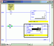
Not sure I understand the B3:10/0. How about using the last bit in the shift, B3:10/5, or the R6:0.UL?

plc5bsl.gif
 
... oops ...

sorry! - you're absolutely right, 93lt1 - i had it right in the program when i tried it out - then i goofed when i typed it into the post - yours looks ok or ...

 
T4:0/DN ----BSL----------------------
-----| |-----------------------| Bit Shift Left |-(EN)
| |
|File : #B3:10 |-(DN)
|Control : R6:0 |
|Bit Address: B3:10/5 |
|Length: 5 |
-----------------------------


as i meant to type earlier ...

next ...

Andrew,

after reading the earlier thread about the block transfer "locking up" problem ... is there any reason why you can't zip the PLC-5/40's file and post it? ... maybe (not very likely - but just maybe) there is something in there that we can help you spot ... if you decide to do this, it would also be helpful to have an accurate slot-by-slot listing of the types of I/O cards located in the "problem" chassis ...
 
Ron,
I think you'll find that the shift takes place first, then bit zero is updated. Due to this, it's bit 6 that should be selected as the seed...or better yet..the UL bit.
 
Yo, Bill,

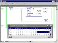
thanks for keeping an eye on me - and I'm probably just misunderstanding what Andrew wants ... but if I've read his chart in the first post of this thread correctly, then he wants bits 0 through 5 to "ripple" on - just one bit on at a time - and one bit for each execution of the BSL - now it's true, he did SAY "five" bits in the text of his post - but his chart clearly shows that "six" bits are actually rippling - so yes, there is certainly some room for misinterpretation - but I just ran this program ...

[attachment]

... on a MicroLogix 1500 and it does ripple the bits (which I've highlighted) just like Andrew's chart specified - I'll try this a little later on a PLC-5/40 system just to confirm that it works the same as on the MicroLogix -

again, thanks for watching,

PS - and incidentally, the reason that I fired up the MicroLogix 1500 in the first place: Andrew mentioned a "1 mS" trigger in his first post - the PLC-5 family doesn't support this fine a resolution - but the MicroLogix 1500 does - so I assumed (gosh, I hate that word) that Andrew must be using a MicroLogix processor - now I'm just guessing here, but maybe he's using "0.01 seconds" for his trigger timer's preset value - so he really meant to say "10 milliseconds" instead when he mentioned his trigger interval -

bsl 2.jpg
 
Last edited:
If you don't understand an instruction, the best thing
you can do is to try it out. If this is out of question
because you don't have the PLC at hand, don't use that
instruction and make your own logic. (well if you are
writing the program, it is all your code regardless if you
know what it does or if it works correctly).
Let's see if this helps:

Shifting complicated?

If you don't understand an instruction, the best thing
you can do is to try it out. If this is out of question
because you don't have the PLC at hand, don't use that
instruction and make your own logic. Instead of
shifting you can use multiply by two (or divide by two
when shifting right).

Shifting "left"?

Well first of all, your bit_0 is on the wrong side
just as 652 is not "two hundred and fifty six".

Here is what you will probably use:
00000001 (bin) = 1 (dec)
00000010 (bin) = 2 (dec)
00000100 (bin) = 4 (dec)
00001000 (bin) = 8 (dec)
00010000 (bin) = 16 (dec)
00100000 (bin) = 32 (dec)

Take a look at it and check if the decimal values
double as I mentioned before. Take a closer look
at the binary side of the equasion and you will
see how "1" shifts moved further to the LEFT.

one milisecond?

what processor you use and what is the scan time?
1ms is pretty much out of question for most
processors unless you use interrupts.

here is a sample program for you to play with
(try to use different B3:10 bit in the first rung
instead of B3:10/6). I've slowed it down so you
have time to see the changes. have fun

SOR BST XIC S:1/15 NXB XIC B3:10/6 BND MOV 1 B3:10 EOR
SOR XIO T4:0/DN BST TON T4:0 0.01 200 0 NXB MUL B3:10 2 B3:10 BND EOR
 

Similar Topics

Dear community, I am trying to find a tool for Allen-Bradley PLCs similar to SiVArch for Siemens PLCs to automatically generate faceplates and...
Replies
0
Views
23
Hi everyone, new to forum. Since very long time i having issue with 1734-AENT module, after some period of time its keep stuck in error (simmilar...
Replies
5
Views
202
Hello, I am new here. I am trying to find good places to sell some surplus items that I have that isnt through ebay. Does anyone have any sources...
Replies
5
Views
329
Hi all, installed on chassis A17 an A/I from Allen-Bradley , problem is what ever I do , all channels are sticked on value 39.9 and cannot change...
Replies
1
Views
127
I have a 1769-L24ER-BB1B and I am trying to flash it to 34xx, its flashing red and faulted, when I try to flash it I get a popup stating it needs...
Replies
14
Views
244
Back
Top Bottom