Dynamic Braking Theory Question

Maxkling

Member
Join Date
Mar 2011
Location
Atlanta
Posts
511
I have a bit of an in-depth question on the operation of dynamic braking / regen. What I know and please correct anything that I am incorrect on...

Anytime the load is operating faster than the drive command, the motor will act as a generator causing a rise in the bus voltage. This is increase is dissipated by a resistor on the DC bus which is controlled by transistor (chopper).

An asynchronous motor will act as a generator when required capacitance is added to the stator and shaft speed is higher than rated motor RPM. The motor can also act as a generator when voltage is added to the stator to excite a field.

So when a VFD is running a motor at 60hz and is commanded to stop 0hz, how can the motor act as a generator when th shaft speed is obviously lower than the motors rated RPM. I’m guessing that through the drives transistors a field is still being generated in the stator allowing the motor to act as a generator. Is this correct?

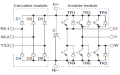
Also how does the power flow backwards through the IGBTs to get back to the bus?
 
Well, while it’s true that the fly back diodes allow reverse current rectification, that’s not really all it takes to function.

Part of your basic assumptions are incorrect. An AC induction motor doesn’t have to run over its base speed, it can be a generator at any time under the following two necessary conditions:
  1. The motor windings are energized to create magnetic flux, and...
  2. The rotor is driven by the load at a speed higher than the RELATIVE rotation of the stator fields.

#1 just means the motor stator must be energized because the entire thing is based on electromagnets, not permanent magnets. No electromagnets, no flux, no magnetic fields, no generation.

#2 doesn’t need to be higher than the RATED speed of the motor, it just needs to be higher than the rotational speed of the stator. So if the VFD is calling for 30Hz and the rotor is driven (by an overhauling load) at the equivalent of 33Hz, that’s a 10% negative slip and the motor will become a generator. Current will then flow back though the diodes acting as a rectifier to charge the DC bus again.

So in Dynamic Braking, the DC bus voltage is monitored and when the voltage exceeds a set threshold level, a 7th transistor (chopper) fires pulses into the resistor to dissipate (transmute) the energy as heat. When a stop command is given, the commanded frequency is lowered to the point where the Motor regenerates and charges the DC bus to that threshold so the chopper fires. Then as the DC bus voltage drops, the reference speed is dropped to keep the motor in that regenerative state, transmuting the kinetic energy of the spinning load into heat in the resistor.

The faster the motor is spinning, the more braking energy there is, but that then means it also suffers from the law of diminishing return, meaning the slower it gets, the less braking energy there is and at some point if there is low friction, the motor stopping time may be undesirably long. So most drives will have the option to turn on what’s called DC Injection Braking that puts DC on one winding of the motor, creating a stationary magnetic field that pulls the rotor into alignment with it, stopping it. The down side of DCIB is that the kinetic energy of the load is then transmuted and absorbed as heat in the rotor. So the trick is to remove MOST of that kinetic energy with Dynamic Braking into the resistor, then finish the job with DCIB when there is only a small amount left.
 
Part of your basic assumptions are incorrect. An AC induction motor doesn’t have to run over its base speed, it can be a generator at any time under the following two necessary conditions:
  1. The motor windings are energized to create magnetic flux, and...
  2. The rotor is driven by the load at a speed higher than the RELATIVE rotation of the stator fields.

I’m guessing that through the drives transistors a field is still being generated in the stator allowing the motor to act as a generator. Is this correct?

So my guess was kind of right, when the drive is commanded to stop, the transistors still fire at your decel rate keeping the stator excited to still generate flux. If the load is forcing the rotor at a speed greater than the flux rotation rate in the stator (with slip correction) then current will flow back through the diodes that bypass the transistors, back into the bus.

My initial thought was when the drive was commanded to stop the IGBT's no longer fired, which is why I was having a hard time understanding how the motor could act as a generator, if the stator was no longer excited and the speed was less than the synchronous speed of the motor.

I understand now, thanks. I was really hoping that "jraef" would reply.

One last question...

When DC injection is DISABLED, how can the drive come to a complete stop? If the drive is open loop, is the deceleration rate linear? So lets say the drive is commanded to stop from 60hz to 0hz, is there a minimum rate the IGBT's will fire and hold at and when the bus voltage stabilizes it assumes the load is stopped? I'm not asking about holding the load when stopped, just how can it get to a complete stop?
 
Well, while it’s true that the fly back diodes allow reverse current rectification, that’s not really all it takes to function.

Part of your basic assumptions are incorrect. An AC induction motor doesn’t have to run over its base speed, it can be a generator at any time under the following two necessary conditions:
  1. The motor windings are energized to create magnetic flux, and...
  2. The rotor is driven by the load at a speed higher than the RELATIVE rotation of the stator fields.

#1 just means the motor stator must be energized because the entire thing is based on electromagnets, not permanent magnets. No electromagnets, no flux, no magnetic fields, no generation.

#2 doesn’t need to be higher than the RATED speed of the motor, it just needs to be higher than the rotational speed of the stator. So if the VFD is calling for 30Hz and the rotor is driven (by an overhauling load) at the equivalent of 33Hz, that’s a 10% negative slip and the motor will become a generator. Current will then flow back though the diodes acting as a rectifier to charge the DC bus again.

So in Dynamic Braking, the DC bus voltage is monitored and when the voltage exceeds a set threshold level, a 7th transistor (chopper) fires pulses into the resistor to dissipate (transmute) the energy as heat. When a stop command is given, the commanded frequency is lowered to the point where the Motor regenerates and charges the DC bus to that threshold so the chopper fires. Then as the DC bus voltage drops, the reference speed is dropped to keep the motor in that regenerative state, transmuting the kinetic energy of the spinning load into heat in the resistor.

The faster the motor is spinning, the more braking energy there is, but that then means it also suffers from the law of diminishing return, meaning the slower it gets, the less braking energy there is and at some point if there is low friction, the motor stopping time may be undesirably long. So most drives will have the option to turn on what’s called DC Injection Braking that puts DC on one winding of the motor, creating a stationary magnetic field that pulls the rotor into alignment with it, stopping it. The down side of DCIB is that the kinetic energy of the load is then transmuted and absorbed as heat in the rotor. So the trick is to remove MOST of that kinetic energy with Dynamic Braking into the resistor, then finish the job with DCIB when there is only a small amount left.

One smart dude. You're awesome. Thanks for the breakdown. It helped me understand a bit more of how it works also.
 
So my guess was kind of right, when the drive is commanded to stop, the transistors still fire at your decel rate keeping the stator excited to still generate flux. If the load is forcing the rotor at a speed greater than the flux rotation rate in the stator (with slip correction) then current will flow back through the diodes that bypass the transistors, back into the bus.

My initial thought was when the drive was commanded to stop the IGBT's no longer fired, which is why I was having a hard time understanding how the motor could act as a generator, if the stator was no longer excited and the speed was less than the synchronous speed of the motor.

I understand now, thanks. I was really hoping that "jraef" would reply.

One last question...

When DC injection is DISABLED, how can the drive come to a complete stop? If the drive is open loop, is the deceleration rate linear? So lets say the drive is commanded to stop from 60hz to 0hz, is there a minimum rate the IGBT's will fire and hold at and when the bus voltage stabilizes it assumes the load is stopped? I'm not asking about holding the load when stopped, just how can it get to a complete stop?
That’s what I was referring to as the law of diminishing returns. In some loads there is friction involved and at some point in the speed drop the remaining inertial energy in the load is lower than the friction so it stops itself. A conveyor is a good example of that. But I’ve seen centrifuges where the DB gets it down quickly to <10 RPM, then it coasts for minutes after that because there is virtually no braking torque left and very very low friction. You have to engage the DCIB on those, or just live with the fact that it went from 45 minutes to spin down on its own to just 10 minutes and the last 3 minutes is getting from 10RPM to the final stop.
 

Similar Topics

I haven't done many applications with braking resistors, but we just put one in for a customer on a 60HP application for a centrifuge. We're...
Replies
21
Views
6,388
I have a customer who has a centrifuge application. The plant engineer did all the calculations on the centrifuge to arrive at a WK^2 of 6458...
Replies
14
Views
3,565
I have a vector drive faulting out. Manual says inspect and test the Braking Resistor. I have never done this procedure before. === From...
Replies
8
Views
2,671
I am not familiar with calculating the resistance value for a DBR. What resistor would I need (ohm + wattage) for a 90vdc, 7.5A, 3/4HP baldor...
Replies
3
Views
2,111
Hello i am trying to set up my ACS350 to dynamically brake a high inertia load. i have noticed that there are a number of digital inputs that...
Replies
11
Views
6,260
Back
Top Bottom