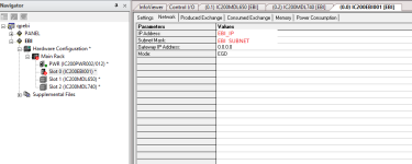
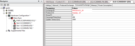
GE QP/QP+ with EBI001 through EGD

JozsefTP

Member
Join Date
Sep 2018
Location
woldwide
Posts
13
Hi!

I have the privilege to take over a project from a guy who didn't even bother to leave backups or proper documentation to a system.
Coming from a Siemens and AB background I consider it cool that the PLC is running on the panel and all the rest is done through the EBI001 modules.

I need to set up a new module for an extension and I can't get it to work.
I get Error 852 (Ethernet Driver): Node 1 [192.168.100.123] moved to unhealthy state due to timeout while waiting for data.

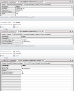
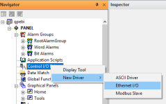
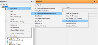
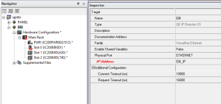
First I tried to copy the settings from the existing setup and then everything else and the kitchen sink from GE documentation and EGD related forum posts. (See screenshots included from an empty project)

Since I don't have the option to set up an EGD exchange for a panel, like it is detailed for PLCs EGD setup documentation I'm sure I'm missing something obvious that I can't find in any documentation or sample case.

Can someone point me into the right direction?


Thank you!
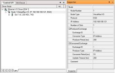
controlio.jpg EBI001.png
 
Are you adding a new input module or a new output module?
If you are adding a new input module you will have to modify the EGD exchange produced by the EBI001 and consumed by the controller.
If you are adding a new output module you will have to modify the EGD exchange produced by the controller and consumed by the EBI001.
Once you download the modified hardware configuration of the remote I/O drop to the EBI001 you will need to cycle power for it to take effect.

I'm adding a new EBI001 module with outputs and inputs. Yes I downloaded the hardware configuration to the EBI001 and cycled the power.

What I'm missing is where do I modify the exchange?
I have only a "logic developer PC with view" without a PLC that has EGD as a component.

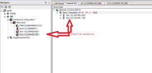
testproject.png
 
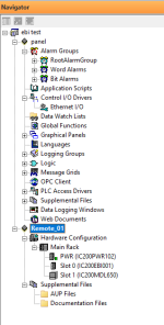
Double click on the "Ethernet I/O" item in the Navigator. That will open a tab labeled "Control I/O" wherein you can fill in the details of the hardware installed in the I/O drop as well as selecting EGD or ModbusTCP as the protocol and setting up the details.
I have set up many EGD exchanges, but always with a PLC, never one with a Quick Panel Control as the front end.
 
This is exactly where I got stuck. In my fist post I attached the screenshots for the configuration I used. There was no option to setup exchange bytes etc.
The weirdest thing is I have a system already working that I can't figure out how to modify or replicate in an independent project....
 
When you double click on the "Ethernet I/O" item you open a tab labeled "Control I/O" which will show items labeled "Node 1" and "Slot 1". Under the properties for "Node 1" Is "Number of slots". Under the properties for each slot is a field where you can enter the model number of the I/O module located there. Proficy will figure out the correct number of bytes in the produced and consumed exchanges based on your module population.
Expand each slot for a list of the variable names assigned to each I/O point on each module.
 
Long story short: after failing to integrate it in the original project during last week I've made a test project just for a panel and the new EBI001 in Proficy 9.5 with the purpose of finding the correct settings to make it work independently (Don't get me started with Win10 / VMware+Win7 / Proficy 8.5 and EBI001 networking issues :mad:)

I've done all the setup in I could find in the Ethernet I/O and the EBI001 target and tested them one-by-one and all 3 modules at the same time.
If I upload only the input modules the Faults LED doesn't light up. While the MDL650 OK LED is on, if I toggle an input nothing happens, no LED, no feedback to the panel.
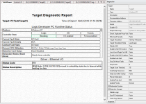
If I add the MDL740 output the Faults LED is on at powerup and the online panel diagnostic says Error 852.

The only thing that is not present in any of the test projects is any ladder logic to turn on the outputs. I don't see a reason if I'm not using the inputs/outputs in any the ladder logic or panels, would trigger faults in the EBI001.

Empty test project attached. :sick::sick::sick:
 
Last edited:
I don't know whether or not it applies to the setup giving you problems, but in the project you posted there are discrepancies between the hardware configuration of the Remote_01 target and node 1 of the Ethernet I/O control I/O driver in the "panel" target. Neither the IP addresses nor the module populations match.
 
Assuming that 3.0.0.127 is the panel in one of my test iterations I tried this setup without success.

I managed to attach the wrong project where I forgot that I changed the IP...

Here is the full project. https://ufile.io/3iqm7
Panel is TRASPORTI at 192.168.100.101, NEW_EBI is at 192.168.100.123
If I use these settings I get the errors mentioned above.
I have no idea what I'm missing that the old system has.
 
Last edited:
In the "Network" tab for the EBI001 module in your "NEW_EBI" target is configured as the same IP address as the "TRASPORTI" target. Both are at 192.168.100.101. NEW_EBI should be 192.168.100.123.
Confusing because it appears that you need to enter the same information in two different places. Once under the properties of the target and again under the "Network" tab of the hardware configuration for the EBI001.
For the two other drops IP addresses match properly.
 
I juggled around the settings looking out for the errors you pointed out in the project you attached and still Error 852.
I'm sure something is running because the STAT LED is on, sadly also the FAULTS LED.

Fun fact: Boss called the guy to assist yesterday and got the answer that we'll never figure it out...

PCTest.png
 

Attachments

  • PCTest_local.zip
    32.5 KB · Views: 0
Last edited:
looking out for the errors you pointed out in the project you attached
The errors I pointed out in post #11 were in the project you linked to in post #10, not the project I attached in post #9. In the project I attached Target1 runs on my laptop (IP address 3.0.0.127) and communicates with an EBI001 (Target 2, IP address 3.0.0.10). When I apply a voltage to the first input point of the MDL240 in my bench setup I see a color change in the left hand circle of Target1. When I click on the right hand circle in Target1 I see the LED associated with the first output point on the MDL330 turn on.
 
I've flown out to a different project last week, but this issue is not going away...
So I'll try to describe step by step what I do, maybe somebody can spot what I'm missing.

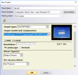
1. create new project with QP+ HMI and control
2. set the PANEL_IP and "True" For Enable I/O in the inspector
3. In Control I/O add Ethernet I/O component
4. Add new target to the project "VersaMax Ethernet"
5. Set up Ethernet I/O:
EBI module IP address
correct slot and module configuration
correct Produced Exchange ID
6. Change the IP address if the EBI modules in the target hardware configuration.
7. Set up Hardware configuration of the new EBI modules
8. Set up EBI configuration in slot0 / Network tab with EBI_IP and subnet mask
9. Set up EBI configuration in slot0 / Produced exchange tab add PANEL_IP
10. Set up EBI configuration in slot0 / Consumed exchange tabadd PRODUCE_ID and PANEL_IP


Did I miss anything?

01.png 02.png 03.png 04.png 05.png
 

Similar Topics

Hi, I am setting up a new GE Versamax drop with modules as below: -IC200EBI001 -IC200PWR102J -IC200CHS003M -IC200MDL742H. However, I find that...
Replies
2
Views
1,937
I haven't encountered problems connecting to a PLC through VM Ware but I am with this particular machine. I'm running Windows 7 on a Windows 10...
Replies
8
Views
110
I'm upgrading an existing machine with a Honeywell HC900 controller, and I'm trying to do some data processing in the controller. I have variables...
Replies
0
Views
39
Hello, I have an automation direct d2 262 plc and C-more HMI EA9T6CL-R. I need to prepare a program, scheduled to be performed on a future date. I...
Replies
1
Views
114
6FX5002-2CD24-1GR0 Via Siemens Sinamics SINAMICS S120 are cuted. I got 1 project that they relocating old Machine to install to new location. Mut...
Replies
1
Views
55
Back
Top Bottom