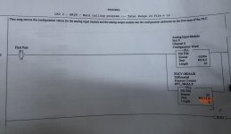
Analogue input Scaling and configuration.

SaadAlbehige

Member
Join Date
Dec 2014
Location
Libya
Posts
15
Hello guys

I am just wondering do I need to set up each channel configuration, including enabling the channel , ranging … if I have already instructions for Scaling “SCP”. in the user program.
If yes, which I doubt, why when I enable the channel and set up the range …etc. the RS logix asks me to insert s rung!! See the pictures please
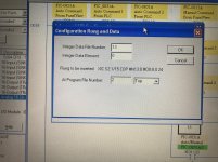
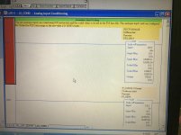
5327C3CD-44CE-4914-ACF6-2C997BAA284E.jpg 6BDD0630-DAFF-474C-9C47-29421D343507.jpg
 
I am only guessing, but it looks like the rung to be inserted is what actually downloads the "configuration file" (Data File N13) into the card itself, and it performs that download only on the first scan (XIC S:1/15) after a transition of the PLC into Run mode (e.g. Program => Run, or recovery from a power cycle).

In other words, the analog card is not physically configured by selecting options and clicking on some [OK] buttons in RSLogix 500, but the actual physical configuration of the card is performed by the PLC program any time that it starts running on its first scan.

If I am wrong, hopefully someone with more experience will correct me.
 
Something to keep in mind with these: The "I" and "O" files are just memory areas inside the CPU, just like the "B", "N", and others. After every scan, the values stored in the "O" data file get sent out to the modules in the corresponding slots. Some analog and thermocouple modules use their output data addresses for configuration (enable, range, etc.). That's what's going on here.


RSLogix is suggesting you add a rung that's executed on the PLC's first scan (S:1/15) to copy the configuration word from internal "N" memory to the output "O" memory so it can then go out to the module. When you check the enable bit for that channel, it toggles bit 15 in the corresponding word in the "N" file that it wants to send to the module every scan. In your case, it looks like the module is in slot 8. What you can do is check bit 15 of each word O:8.x to see if they're toggled on. Bit O:8.0/15 is for channel 1, O:8.1/15 is for channel 2, etc. You can probably just toggle on bit 15 for the correct word without letting it create the rung, especially if a cross reference shows that those words aren't written anywhere in the program.


Can you share your RSLogix file?
 
in a slc 500 plc using the analog modules, you need to have a first scan channel configuration rung for each channel / the card (it's been a while since i did this). these runs tell the module what it is and how its used.
regards,
james
 
in a slc 500 plc using the analog modules, you need to have a first scan channel configuration rung for each channel / the card (it's been a while since i did this). these runs tell the module what it is and how its used.
regards,
james
Thanks for your reply.
What if I already have First Scan rung with FIL instructions for the analogue I/O as well as SCP scaling! Do I still need to configure the I/O channels, I wonder?
 
Something to keep in mind with these: The "I" and "O" files are just memory areas inside the CPU, just like the "B", "N", and others. After every scan, the values stored in the "O" data file get sent out to the modules in the corresponding slots. Some analog and thermocouple modules use their output data addresses for configuration (enable, range, etc.). That's what's going on here.


RSLogix is suggesting you add a rung that's executed on the PLC's first scan (S:1/15) to copy the configuration word from internal "N" memory to the output "O" memory so it can then go out to the module. When you check the enable bit for that channel, it toggles bit 15 in the corresponding word in the "N" file that it wants to send to the module every scan. In your case, it looks like the module is in slot 8. What you can do is check bit 15 of each word O:8.x to see if they're toggled on. Bit O:8.0/15 is for channel 1, O:8.1/15 is for channel 2, etc. You can probably just toggle on bit 15 for the correct word without letting it create the rung, especially if a cross reference shows that those words aren't written anywhere in the program.


Can you share your RSLogix file?
Hello

Thank you very much for your reply.
I have checked bit 15 in all channels(O:8.0/15 to O:8.15/5), they are not toggled.
Of course, I can toggle them to enable the channels but when I configure the channel in the I/O configuration , still recommends creating rung for first scan.

I have checked the program, there is First Scan with FIL instruction for the analogue I/Os?
I do not want to create another First Scan rung with Copy Instructions as this will apparently overwrite the value and confusion might occur.

As I already have First Scan with FIL instructions and SCP in my program , I am wondering if it is still necessarily to configure the channels?

Thanks
 
SCP is different than configuration.


Can you post a screenshot or PDF of what your FIL (FLL?) instructions look like?


If the created rung duplicates what your FIL instructions do, then you can delete the created rung later.
 
SCP is different than configuration.


Can you post a screenshot or PDF of what your FIL (FLL?) instructions look like?


If the created rung duplicates what your FIL instructions do, then you can delete the created rung later.
kindly see the attachment of FLL instructions. However, I already tried the new rung then delete it, when I check back the configuration, no configuration found?

186F4D51-0A47-43C6-99A1-1EEB02F4DE45.jpg
 
Last edited:
... However, I already tried the new rung then delete it, when I check back the configuration, no configuration found?


That's odd. Maybe RSLogix maintains the configuration in (via?) that rung that it creates and the Data File it uses to feed it. If that is the case, I suggest you ensure what that created rung does is functionally the same as your first-pass FLL instructions, then delete your FLL instructions.
 

Similar Topics

Hi, I have a ControlLogix system with 1756-IF16 analogue inputs. I can't scale the inputs at the card as there is a requirement to facilitate...
Replies
11
Views
260
There have been a number of posts asking about scaling so I thought this may help. The formula is: Out := ((Variable_In - ZeroIn) / (SpanIn -...
Replies
11
Views
6,461
Hi, In a Siemens, when you read an analogue input from a standard modul you read in the range 0-27648 INT value. What is the range in a TSX...
Replies
1
Views
1,652
Hi all you gurus, I've got a CPU942b which is reading an analogue input, and scaling it, but I'm getting odd results. In short, what the code...
Replies
5
Views
3,618
Hi, I have a device which is giving out a 4 -20mA signal but the ADC's on the PLC channel do not match. The supplier is saying the channel needs...
Replies
2
Views
759
Back
Top Bottom