Frequency measurement methods. PLL?

naturephoenix

Member
Join Date
Jan 2015
Location
Vienn
Posts
181
Hello,

I got voltage measurement via AI module. AI module cycle is 50microsec. My PLC cycle is 1ms.

So every 1ms I am getting 20 samples from which I calculate efective value of voltage. Now I need to calculate frequency of my measuring unit (Voltage in this case).

It's generator voltage so basically nominal frequency is gonna be around 50Hz and it's sine wave.

I'm wondering for what kind of methods are the best.

1. First what gets on my mind is zero crossing method. That means every 1ms I'm checking whether

some sample (out of 20 samles) went over zero.


...

Some of the colleagues mentioned to me PLL method, but as far as I can understand this method is used to compare two different frequencies and eventually to make them equal. I don't know how would I use that for my voltage frequency measurement.


Thx in advance.
 
I think that if all you need to do is determine the frequency, a low pass filter and a zero crossing detector is the way to go. If you need to determine the phase angle of the waveform for something like synchronising to it or accurately firing a thyristor then you would look at PLLs or second order generalised integrators.
 
Does the AI card save all 20 samples and then transfer those 20 samples to the PLC at 1mS intervals?
 
Hello,

I got voltage measurement via AI module. AI module cycle is 50microsec. My PLC cycle is 1ms.

So every 1ms I am getting 20 samples from which I calculate efective value of voltage. Now I need to calculate frequency of my measuring unit (Voltage in this case).

It's generator voltage so basically nominal frequency is gonna be around 50Hz and it's sine wave.

I'm wondering for what kind of methods are the best.

1. First what gets on my mind is zero crossing method. That means every 1ms I'm checking whether

some sample (out of 20 samles) went over zero.


...

Some of the colleagues mentioned to me PLL method, but as far as I can understand this method is used to compare two different frequencies and eventually to make them equal. I don't know how would I use that for my voltage frequency measurement.


Thx in advance.

You would get a reference 50hz and compare it with the PLL. Probably wouldnt work in this case for you.
 
As you haven't given any performance specs, I would recommend zero crossing as it is simpler code.

PLL will give you a more dynamic (faster) response though, which is more appropriate in some cases. My understanding of PLL:

Start by assuming that Amplitude, phase and frequency are 560V, 0pi and 50Hz.

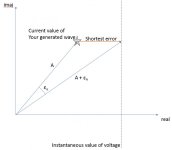
Based on the measured instantaneous voltage, you will have an amplitude error and an angle error as shown in the diagram. Using a simple filter function, your three variables will approach the actual value.

Amplitude = Amplitude + k0 * error_Amplitude
phase = phase + k_1 * error_angle
frequency = frequency + k_2 * error_angle

once you have locked on (both errors approaching zero), your sine wave generator will have Amplitude = V_rms*sqrt(2), frequency = frequency you are interested to.

PLL with amplitude.jpg
 
What plc and what Ai module? The ai seems unrealistic fast.

Have you considered a special Ai module that does the calculation or a separate power monitor?
 
Hello, thx on quick replies. PLC is Beckoff CX2030-0125 and Card is EL3783. CARD just gives samples 20 inside 1ms. In PLC you have to do something with it. Regarding this PLL i dont understand how Amplitude=Amplitude +k*errorAmplitude will eventually give me good measuring value of frequency. This looks like P governor. I MEAN what I do with result of this equation? And what if I assume bad? I assume its 50Hz. Lets say in reallity is 20Hz. REAL ERROR IS 30HZ. Amplitude I can read from AI card but not sure what it would be Phase, I mean I hot only samples of voltage and not of its angle. OR I still need to calculate frequency with zero crossing method and use this as an correction with frequency = frequency + k*FreqError. FreqError is calculated by assumed(50)-my measured value.
 
Last edited:
Personally, I'd be using separate voltage and frequency transducers to feed 4-20mA signals into the PLC.

The cost of 3 phase power meters these days makes it cost effective to just read all these parameters from a meter, assuming this is for monitoring purposes.

If you're trying to do something like mains / gen synchronization then a PLC is not the right tool for the job.
 
You could assume 30000V, 900000Hz and any phase angle, it will just take longer to converge on a solution.
Frequency = Frequency + k2 * phase_error is a filter, if k2 < 1.

You don't actually know what the angle is, you only know the real component of voltage. This gives the dashed line of possible values in the diagram. Choose the closest point on that line to where your signal generator is, ie use the imaginary component you got from your signal generator.

Thx on your tries but I still don't get it. Will read some PDFs and examples.

What I got now is that to calculate frequency with PLL method I need Amplitude and phase? Amplitude I can get from my measurements by taking samples but phase not sure how to. Maybe like taking care in which AI cycle (time) I got specific sample.

No matter what I can not get this equations without small example:
Amplitude = Amplitude + k0 * error_Amplitude
phase = phase + k_1 * error_angle
frequency = frequency + k_2 * error_angle

Amplitude = 10, k0= 0.5, AssumedAmplitude = 15;
Amplitude(1) = 10 + 0.5 * (15 - 10)
Next cycle:
Amplitude(2) = 12.5 + 0.5 * (15-12.5)...
IS this correct?
 
I have looked at a similar problem to this for a thyristor rectifier controller where I had to be able to determine the phase of a power source with a lot of noise, harmonics and wildly varying frequency. The method I used is shown in Fig. 3 of the attached paper.

https://s3.amazonaws.com/academia.e...=Grid_synchronization_of_power_converters.pdf

It isn't too difficult to implement and it worked really effectively for me. In your case, you can read omega' directly and convert it to Hz. The only thing that I'm not sure about is the relatively low number of PLC cycles per period of the input waveform. When I did this, I was using a DSP with a much quicker program cycle.
Will take a look thank you.

I can reduce plc cyvle time to 400 microsec. Ai ard is still on 50microsec.
 

Similar Topics

I'm reading someone else manual inside which is described speed measuremnt by measuring the time in between 2 signals. It says "The 24VDC...
Replies
6
Views
2,604
Hi - off topic but hopefully someone has some experience. I am looking to install a level detection unit for monitoring fill levels in bottles...
Replies
3
Views
1,909
Hi, I have an application where I need to measure the speed of a rotating roll on a Siemens S7-400 system. I have an incremental encoder connected...
Replies
5
Views
5,842
Hi, I have an application where I need to measure the speed of a rotating roll on a Siemens S7-400 system. I have an incremental encoder connected...
Replies
0
Views
2,971
Hello guys, I am new to this forum and have some problems with my PowerFlex755 EENET frequency inverter. I want to do a point to point...
Replies
9
Views
381
Back
Top Bottom