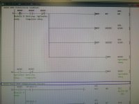
RTD conversion enabled. What's going on here?

Mas01

Member
Join Date
Oct 2020
Location
Leicester, England
Posts
1,105
Rungs 0 to 32.
Can anyone explain what's going on here?
What does "H" represent?
Why those particular values (H0 and H2222)?
R0S0 is rack 0 slot 0 , which is an 8-channel RTD input card. Thanks!

IMG_20201124_153440.jpg
 
Thanks, I had no idea it was hex!
I've learnt something today!


Maybe, I am only guessing; often the H is at the end for hex radix; a letter at the front usually says summat else about the number (where in memory, etc).


parky will know for sure, but see page 6-40 here.


Ah, found this in that manual, p. 5-10:

  • Enter a constant value headed by K, H, E or '''' to ensure that it can beidentified as a decimal, hexadecimal, actual number or character stringconstant.
 
Last edited:
Maybe, I am only guessing; often the H is at the end for hex radix; a letter at the front usually says summat else about the number (where in memory, etc).


parky will know for sure, but see page 6-40 here.


Ah, found this in that manual, p. 5-10:

  • Enter a constant value headed by K, H, E or '''' to ensure that it can beidentified as a decimal, hexadecimal, actual number or character stringconstant.

Good detective work. Cheers!
 
Correct the H denotes Hex K denotes integer E denotes float.
You can write to those with integer as well but in this case it is writing to buffer memory of an intelligent card and often the buffer memory word can be split into bytes nibbles or bits in this case it is to set the card to a particular mode.
Cannot remember exactly the buffer memory addresses but it is probably setting either 4 or 8 of the channels to a particular mode like PT100 sensor type in many cases each channel is assigned to a nibble (4 bits) for example 0/1/2/3
so writing to one word H3333 will set the 4 channels to that mode.
There are many buffer memory areas assigned to intelligent cards probably 255 although some are write only or read only and some cannot be written or read from as they are used internally.
Nowadays it is rare to set up intelligent cards this way as there are add on utilities to configure the cards like GXConfigurator-AD for analogue to digital cards.

Ah, I think another penny's dropped.
We've got many PT100 sensors in the system, so you could be right. So writing H2222 will set up 4 of the channels, and then on the next rung it does the same again for the other 4 channels...I think.
 
Here is the manual, there is a lot to take in if you want to understand how it works, look at section 3 it gives the list & explanations of the buffer memories, there are many parameters that could be used like type of PT100, ranges, filters, offset & span settings the list is endless, on your other post regarding the subtraction of a value as an offset this could have been done within the program for calibration purposes but it's a lot of work so most people do not bother just add or subtract a bit around the expected range. Using the configurator is far easier.
I have just had a quick look at those addresses 164 & 165 and these seem to be offset settings but again chinenglish manuals do not make it very clear so are not the mode as such, I have only used the FX PT modules on all Q series I used 4-20ma and head converters in the PT100 probes, this gave us a quick way to calibrate them without touching the PLC code or pages of settings on HMI's.
https://dl.mitsubishielectric.com/dl/fa/document/manual/plc/sh080142/sh080142o.pdf
 
Last edited:
Here is the manual, there is a lot to take in if you want to understand how it works, look at section 3 it gives the list & explanations of the buffer memories, there are many parameters that could be used like type of PT100, ranges, filters, offset & span settings the list is endless, on your other post regarding the subtraction of a value as an offset this could have been done within the program for calibration purposes but it's a lot of work so most people do not bother just add or subtract a bit around the expected range. Using the configurator is far easier.
I have just had a quick look at those addresses 164 & 165 and these seem to be offset settings but again chinenglish manuals do not make it very clear so are not the mode as such, I have only used the FX PT modules on all Q series I used 4-20ma and head converters in the PT100 probes, this gave us a quick way to calibrate them without touching the PLC code or pages of settings on HMI's.
https://dl.mitsubishielectric.com/dl/fa/document/manual/plc/sh080142/sh080142o.pdf
Thanks again.
That section 3 is really useful. e.g. Section 3.4.7
CH measured temperature value (16bit) (Un\G11 to 14)


Similar Topics

Good Morning , I have a RTD , that I would like to wire into a 1756-IF8 Analog Input Card. Would you all a simple wiring diagram , of what...
Replies
4
Views
1,188
Good Afternoon , It seems like we always have problems with using Type J Thermocouples with our slip rings . Would using a RTD at 10...
Replies
6
Views
1,634
We are running a power flex 70 connected to a Delta V and I cannot get the drive to start because I am getting a STOP ASSERTD message on my HMI. I...
Replies
4
Views
2,988
I am working on an installation that will require sensor cabling interconnecting sensors to PLC subject to outdoor temperatures. Will the ambient...
Replies
3
Views
2,054
Hello! I have RTD sensor with 4 wire and shield ( 2 red wire + 2 white wire + Shield) and I want to connect to 1734-IR2 module. But in the manual...
Replies
2
Views
1,423
Back
Top Bottom