Non synchronized vision-based conveyor rejection

Starbot1

Member
Join Date
Oct 2021
Location
Boston
Posts
14
Hi all,

IÂ’m working on a project where a vision system takes an image of the conveyor about 2 ft in length and with full width. The conveyor is filled with product and the product is layed in columns or lanes just that if 4 lanes exist, 4 rejection paddles exist at the end of the conveyor.

The vision system works on machine learning and snaps a full width image, returning the x,y positions of any rejected product. The issue is that image comes in an indiscriminate amount of time. Sometimes 1/5 of a second sometimes 3/5th, etc.

If I want the rejection paddles on some type of shift register, how do I accomplish this with regard to the in discriminate timing? Should I simply wait to populate the shift register after 3/5th of a second, the maximum it would ever take? When and how do I trigger each image? After the encoder has advanced another 2ft?

Thanks for any tips or suggestions!!
 
Welcome to the forum, @Startbot1!

When you write "The issue is that image comes in an indiscriminate amount of time," do you mean that

  • you don't know when the image was taken,
OR

  • you do know when the image was taken, but the product has moved an arbitrary, but known, amount of of time (~distance) on the conveyor, since the image was taken?
With the former, I think you are probably up the proverbial creek.

With the latter, I think all that needs to be done is to write 1s into the shift (and shifting) register for any rejected lane at the rejected [X,Y] location adjusted for time since the image was taken, until the next image comes in; assuming the shift register is initially loaded with a 0.

That is a general statement, but there is a lot we do not know: does the product comprise discrete objects, or is it a continuous stream e.g. windrows of powder or similar?
 
The latter— we know when the image was taken and how long it took but yes the length it took to process is arbitrary. You’re right we know how many meters the product has passed I suppose given the time and encoder count. How do I adjust or shift for time exactly? Forgive my ignorance here! Using click plc ladder logic.

Thank you for your reply!

The product is discrete but variable in size. Actually — agricultural in nature.
 
Summary

It's all about the bookkeeping.

Details

Does click plc have a bit-shift-left (BSL) or bit-shift-right (BSR) instruction, and can that instruction span multiple words?

Say it does and can, and you have

  • a sprocket wheel on the conveyor roller
    • such that some number, say 91, of teeth are equivalent to two feet of conveyor movement,
  • and a prox detecting each sprocket tooth that goes near the fixed prox position
  • If you don't have sprocket teeth and/or a prox, then
    • say the conveyor moves at a constant rate,
      • say two feet in 9.1s,
        • which is 91 100ms periods
Either way you should be able to generate 91 pulses over two feet of conveyor movment.

Allocate a shift register for each lane that is an array of six 16-bit words (96 bit; 96 >- 91).

At each pulse (tooth prox or 100ms pulse), push (shift) a 0 bit onto the shift register, using the BSL instruction. That represents the new quantum of product that has just been placed onto the beginning of the conveyor, and the BSL instruction that does the shift also shifts all other bits one to the left, representing the movement since the previous pulse.

If that new quantum of product is bad, the PLC model does not know it yet, and it assumes the product is good, which is why it pushed a 0, but it will need to know if the product is bad before that bit moves 91 times from the start and gets to bit position 91 (bit 11 out of [0..15], in word 5 out of [0..5]).

So at some point, the image is taken, and say X represents the lane (cross-conveyor) position, and Y represents the location of a bad product in the along-conveyor position. You might need to scale Y to figure out which bit, [0..91], it represents, but that should be straightforward; let's say Y in the image converts to YbitImage at the time the image was taken.

If you know

  • the image was taken some Tdelay seconds ago, i.e. between the time of the image and the time of the current scan, and
  • the conveyor moves 91 pulses in Tperiod seconds,
Then that means the bad product at YbitImage has moved another Tdelay * (91/Tperiod) pulses between the time of the image and the time of the current scan.

  • So on the scan when receive you the image and convert Y to YbitImage, you calculate the current position of the bad product as
    • YbitNow = YbitImage + (Tdelay * 91 / Tperiod)
      • Obviously you will want to be careful with rounding and such;
      • a much higher number of pulses per foot will improve the accuracy.
Still on the current scan when the image was received, the PLC model knows that bit YbitNow out of [0..91], in lane X, represents a bad product, so it needs to change the 0 at that location, YbitNow, to a 1. I don't know how click PLCs address bits using indirect addressing, but you will need to convert YbitNow into a [word,bit_in_word] pair:

  • Ybit_in_wordNow = YbitNow AND 15 ### Assumes AND is a bit-wise instruction
  • YwordNow = (YbitNow - Ybit_in_wordNow) / 16
Then all that is left is to set bit [Ybit_in_wordNow] of word [YwordNow], using the set/latch instruction. When that bit gets to bit position 91, it will cause the diverter paddles to activate.

Caveats

  • It would probably work best to add a small offset, as a number of bits, to the Y-to-Ybit conversion to extend the "bad" bit designation beyond (downstream-conveyor) the nominal Ybit result, and to set several contiguous bits from that location back (upstream-conveyor) towards the beginning of the conveyor to ensure the paddles divert the bad product.
    • How much of an offset and how many contiguous bits will depend on the process, how big the products are in units of bit position, and how much, or little, of a gap there may between products.
  • The [91/Tperiod] ratio represents the speed of the conveyor in pulses per second.
    • if the conveyor speed may change, then it may make sense to make that (91/Tperiod) speed a variable i.e. measured and calculated quantity*, so the system will continue to work even if the conveyor speed changes.
      • * that calculated quantity may be scaled from a speed reference, or from a continually measured number of pulses per so many seconds.
      • This is a problem if the pulses are not based on a prox detecting sprocket teeth, and will require a somewhat different approach.
  • If click plc does not have a multi-word capable BSL instruction, you will have to build one capable of handling multiple shift registers (lanes).
 
Well gosh-- all i can say is thank you. Thank you very much! I will digest this and try your suggestions. I will likely do my best to execute, then come back as I progress.

We only have one Shift Register function available to us in Click PLC (assuming it's a BSL), and it can only address bits C0001-C2000, so I suppose even if I use multiple shift registers, I will be limited in my buffer? Am I in trouble that we do not have a bit shift right?

Can this be done with multiple shift registers using different bits and the same clock input?
 
We only have one Shift Register function available to us in Click PLC (assuming it's a BSL), and it can only address bits C0001-C2000, so I suppose even if I use multiple shift registers, I will be limited in my buffer? Am I in trouble that we do not have a bit shift right?

I have no experience with Click PLC, but if that means at most 2000 bits are available to BSL or equivalent, then that is all you have e.g. if 4 lanes each then at most 500 bits per lane, possibly rounded down to next lower multiple of 16 i.e. 496.

You only need one of BSL or BSR, but it would be unlikely to have only one. BSR is functionally the same as BSL, except

  • Push (shift) the 0 at the last position (bit position 91 = [word=5;bit_in_word=11] for the 91-pulse mode)
  • The conversion from Y to YbitImage and from YbitImage to YbitNow goes backward from bit position 91 towards bit position 0 in the downstream-conveyor direction
  • The rejection diverter paddles are controlled by bit position 0 = [word=0; bit_in_word=0].

Can this be done with multiple shift registers using different bits and the same clock input?

Yes; usually the number of bits to shift (92 in my example) is an inputs parameter to the BSL, although that length may need to be a multiple of 8 or 16. Or, since they all shift at once, put the registers end-to-end and shift the entire thing at once, so 0-91 is lane 1, 92-183 is lane 2, 184-275 is lane 2, etc., and the length passed to the BSL is (#lanes x 92), and you push a 0 bit to the BSL, but also reset bits 92, 184, 276, etc. on each pulse rising edge.


Ooh, interesting idea: parallel via FIFO instead serial with BSL. Make an integer (word) array FIFO, each bit in a word models one lane, so bit 0 of all words in the array models the first lane, and the word position in the array models the position of that bit on the conveyor. 8- or 16-bit words in the FIFO means up to 8 or 16 lanes.

P.S. I assume the shift (BSL/BSR) and the FIFO Load/Unload are all triggered by a rising edge of some kind e.g. of a prox or 100ms timer .Q.
 
OK the truth should come out-- I've never written LL before... strictly C and structured text, python, arduino, that ****.

So this is all crammed into one rung and I know that's bad. I'm wondering where I separate the rungs, in this case.

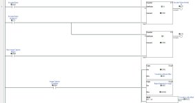
Anyway, I've attached images of my work thus far. I take an encoder bit and divide by 10 because it's currently a 360p/r encoder so it will eat up my shift register too quickly.

A second counter is used for the division, but I am also using it's total count as the "image delay". I.e. the number of encoder pulses that has passed since the image was initiated.

Once the image is back and I have my "Ybitimage" value, I use that value (DS1) and add the offset to get to Ybitnow (DS2)? If that's right I am using indirect addressing in the form of C[DS2] to flip the bit at desired position in the shift register. C[interger] is the notation for indirect addressing for click PLC.

I found out the to do BSR instead of BSL, I just reverse the bit addresses in the function block, for what that's worth.

Would appreciate any schooling 👨🏻‍🏫 before getting the actual PLC hardware tomorrow to try it out. I'm particularly concerned with my lack of understanding in serializing the program into rungs.

Summary

It's all about the bookkeeping.

Details

Does click plc have a bit-shift-left (BSL) or bit-shift-right (BSR) instruction, and can that instruction span multiple words?

Say it does and can, and you have

  • a sprocket wheel on the conveyor roller
    • such that some number, say 91, of teeth are equivalent to two feet of conveyor movement,
  • and a prox detecting each sprocket tooth that goes near the fixed prox position
  • If you don't have sprocket teeth and/or a prox, then
    • say the conveyor moves at a constant rate,
      • say two feet in 9.1s,
        • which is 91 100ms periods
Either way you should be able to generate 91 pulses over two feet of conveyor movment.

Allocate a shift register for each lane that is an array of six 16-bit words (96 bit; 96 >- 91).

At each pulse (tooth prox or 100ms pulse), push (shift) a 0 bit onto the shift register, using the BSL instruction. That represents the new quantum of product that has just been placed onto the beginning of the conveyor, and the BSL instruction that does the shift also shifts all other bits one to the left, representing the movement since the previous pulse.

If that new quantum of product is bad, the PLC model does not know it yet, and it assumes the product is good, which is why it pushed a 0, but it will need to know if the product is bad before that bit moves 91 times from the start and gets to bit position 91 (bit 11 out of [0..15], in word 5 out of [0..5]).

So at some point, the image is taken, and say X represents the lane (cross-conveyor) position, and Y represents the location of a bad product in the along-conveyor position. You might need to scale Y to figure out which bit, [0..91], it represents, but that should be straightforward; let's say Y in the image converts to YbitImage at the time the image was taken.

If you know

  • the image was taken some Tdelay seconds ago, i.e. between the time of the image and the time of the current scan, and
  • the conveyor moves 91 pulses in Tperiod seconds,
Then that means the bad product at YbitImage has moved another Tdelay * (91/Tperiod) pulses between the time of the image and the time of the current scan.

  • So on the scan when receive you the image and convert Y to YbitImage, you calculate the current position of the bad product as
    • YbitNow = YbitImage + (Tdelay * 91 / Tperiod)
      • Obviously you will want to be careful with rounding and such;
      • a much higher number of pulses per foot will improve the accuracy.
Still on the current scan when the image was received, the PLC model knows that bit YbitNow out of [0..91], in lane X, represents a bad product, so it needs to change the 0 at that location, YbitNow, to a 1. I don't know how click PLCs address bits using indirect addressing, but you will need to convert YbitNow into a [word,bit_in_word] pair:

  • Ybit_in_wordNow = YbitNow AND 15 ### Assumes AND is a bit-wise instruction
  • YwordNow = (YbitNow - Ybit_in_wordNow) / 16
Then all that is left is to set bit [Ybit_in_wordNow] of word [YwordNow], using the set/latch instruction. When that bit gets to bit position 91, it will cause the diverter paddles to activate.

Caveats

  • It would probably work best to add a small offset, as a number of bits, to the Y-to-Ybit conversion to extend the "bad" bit designation beyond (downstream-conveyor) the nominal Ybit result, and to set several contiguous bits from that location back (upstream-conveyor) towards the beginning of the conveyor to ensure the paddles divert the bad product.
    • How much of an offset and how many contiguous bits will depend on the process, how big the products are in units of bit position, and how much, or little, of a gap there may between products.
  • The [91/Tperiod] ratio represents the speed of the conveyor in pulses per second.
    • if the conveyor speed may change, then it may make sense to make that (91/Tperiod) speed a variable i.e. measured and calculated quantity*, so the system will continue to work even if the conveyor speed changes.
      • * that calculated quantity may be scaled from a speed reference, or from a continually measured number of pulses per so many seconds.
      • This is a problem if the pulses are not based on a prox detecting sprocket teeth, and will require a somewhat different approach.
  • If click plc does not have a multi-word capable BSL instruction, you will have to build one capable of handling multiple shift registers (lanes).

PLC1.JPG PLC2.JPG
 
I think it would be doable the trick is to track each set of products
a pulse generater of some type to connected to the conveyor or you could possabely detect the leading edge of the produce in the conveyor use an up down counter
I would not use a timer the conveyor speed / time woul dnot be reliable enought to do it
I would need to have a lot more details to really get into it
 
OK the truth should come out-- I've never written LL before... strictly C and structured text, python, arduino, that ****.
No matter the language, coding is always the same thing: modeling summat IRL. The only significant design choice is the level of fidelity i.e. how much of reality does the program need to model (e.g. it typically will not need to model operator break times, but it might); after that everything is bookkeeping of bits.
So this is all crammed into one rung and I know that's bad. I'm wondering where I separate the rungs, in this case.
Ladder is interpreted left-to-right, then top-to-bottom. That means we need to arrange the rungs so the model executes its individual steps in the right order. That is also a difference between digital, CPU- and program-based ladder logic and analog, wire_relay-based ladder logic.

Anyway, I've attached images of my work thus far. I take an encoder bit and divide by 10 because it's currently a 360p/r encoder so it will eat up my shift register too quickly.
Nice.

A second counter is used for the division, but I am also using it's total count as the "image delay". I.e. the number of encoder pulses that has passed since the image was initiated.
Ooh, really nice. Note that [X005 Image Capture Complete] needs to be a oneshot i.e. needs to have a value of 1 one scan only (Vasily) when image capture has transitioned to complete since the previous scan.

Once the image is back and I have my "Ybitimage" value, I use that value (DS1) and add the offset to get to Ybitnow (DS2)? If that's right I am using indirect addressing in the form of C[DS2] to flip the bit at desired position in the shift register. C[interger] is the notation for indirect addressing for click PLC.
I am not an expert on Click PLC LL syntax, but I think, when [X005 Image Capture Complete] is 1, that


  • the [COPY CTD2 DS1] instruction should be deleted
  • and the remaining two instructions should be reversed in order
    • the math needs to be rewritten to add DS1 (YbitImage) and CTD2 encoder/10 pulses since image capture) to get the result DS2 (YbitNow)
    • then the [COPY X001 C[DS2]] should execute after DS2 is calculated.

I found out the to do BSR instead of BSL, I just reverse the bit addresses in the function block, for what that's worth.
I am not sure calling it BSL or BSR, or even referring to left or right, makes sense; it looks like bits get shifted from position 1 (C1) to position 500 (C500).
Would appreciate any schooling 👨🏻‍🏫 before getting the actual PLC hardware tomorrow to try it out. I'm particularly concerned with my lack of understanding in serializing the program into rungs.

The [Data] input to the [Shift Register] instruction should not be X001; it should be a bit that is always 0 (or a rung that is always false).


This is because the model assumes products are either good (bit = 0) or not present (also bit = 0) at the beginning of the conveyor at each encoder one-shot, one-scan pulse. Only later, when the Image Capture Complete becomes 1, do the MATH and COPY instructions change that bit, which is at position C[DS2], IF and only IF X001 is 1 i.e. a rejected product is at position DS2.
 
I'm not sure how to give karma here, but 🍺 to drbitboy. Perhaps the most helpful AND encouraging individual on the internet. It's usually rough out there, and you've gone ahead and done nothing but help a stranger out, and not just once.

I've made some progress here in organizing the program left/right, up/down. I have not made progress on the logic yet (the copies, etc). I have realized that the shift register data should always be 0, like the Dr. said, though here I just used a bit set to false (when I was testing that section).

I have begun to implement the Modbus TCP communication, which will talk to our vision PC. So far, it worked readily to both read registers and write coils. We will write the X,Y values of the rejects to Modbus registers, then we will set a coil high to signal the PLC that the data is ready and the shifted and offset bit should be written. Is this the right way to use Modbus?

Anyway, I will continue to update with my progress and thanks again, PLCTalk members!
 
We're sorting using a high speed machine learning algorithm developed for the specific product (medical/commercial cannabis). There is no differentiating features such as color or size. It really has to be ML on the vision side, and there we've worked for years to train the algorithm (15fps) and I've hired engineers to do the heavy lifting on the B&R PLCs, etc. Now I am trying a sorting project on my own (initial application was called "trimming"), as a learning exercise as much as a proof of concept!

I am interested in the challenges we may face as we are looking to move the belts around 12-18fpm. The algorithms processes a full frame (2ft x 3ft roughly) in about .05 seconds.
 
Last edited:
Why didn't you provide this information at the beginning? At least your belt doesn't move that fast. I think you are doing it wrong.

I would use a line scan camera(s). These can scan fast enough to keep up with the encoder.
One camera will have problems seeing outside edges of what you are scanning. Two line scan cameras scanning for the sides would see more.
Since the line scan cameras are fast, they can be synchronized with the conveyor encoder. Use should be able to do one scan per encoder count. Use an encoder that has the most resolution that your CPUI and lines scan cameras can handle. Use a real CPU, not a PLC to handle the queue. A circular queue of 32 bits could handle 32 lanes if necessary. Fewer if you want to use two bits for each lane for 4 categories. Example, good, iffy, bad, very bad.

I really think you are wasting your time trying to do all of this in a PLC.
 
Again, I think you're trivializing the vision side. A line scan camera does not tell you much without an algorithm. And ML algorithms like context. I.e. one line will not anything for us. You need a full 2MP frame so that the product can be categorized by a ML algorithm (which can not work on a line sample alone, it must have context and see the full product at once).

Again, you are acting as if this is a plug and play solution I can grab from Cognex. I assure you, it can not be done that way, even with their D900 deep learning camera. They are lightyears behind ML when it comes to categorization or any organic analysis.

Why didn't you provide this information at the beginning? At least your belt doesn't move that fast. I think you are doing it wrong.

I would use a line scan camera(s). These can scan fast enough to keep up with the encoder.
One camera will have problems seeing outside edges of what you are scanning. Two line scan cameras scanning for the sides would see more.
Since the line scan cameras are fast, they can be synchronized with the conveyor encoder. Use should be able to do one scan per encoder count. Use an encoder that has the most resolution that your CPUI and lines scan cameras can handle. Use a real CPU, not a PLC to handle the queue. A circular queue of 32 bits could handle 32 lanes if necessary. Fewer if you want to use two bits for each lane for 4 categories. Example, good, iffy, bad, very bad.

I really think you are wasting your time trying to do all of this in a PLC.
 

Similar Topics

if we need to take back up of Siemens CPU(s7300 /s7400) with non siemens slave profibus nodes without their gsd files and when we restore it in...
Replies
0
Views
82
Hi all, I have installed a SICK AFM60A-S4IB018x12 encoder to Allen-Bradley CompactLogix PLC and configured its parameters via AOI provided by...
Replies
0
Views
95
Hi, I'm trying to understand a couple of things with a feedback signals that are used in a SRP/CS that I'm working with. Quick disclaimer: I'm...
Replies
2
Views
530
Hello, has anyone ever been caught in this situation? You have redundant CPUs, fieldbus is PROFINET, there are some devices which don't have the...
Replies
0
Views
514
Looking to see if there is any sort of publication or details on if I can tie a 1794 AENT module to a 3rd party eth/ip scanner (happens to be opto...
Replies
2
Views
703
Back
Top Bottom