4-20ma less than 4 ma HMI reading: RSLogix

noob

Member
Join Date
Mar 2020
Location
ontario
Posts
26
Hello,
RSLogix 500, a 4-20ma analog input to PLC is scaled for 0 to 100 psi. It is displayed as 0 to 100 psi on HMI, I want to make sure that for less than 4 ma current, HMI should show negative pressure. Right now, even for less than 4ma, HMI just shows zero pressure, doesn't show anything negative.
Is it a scaling issue? Please guide. For 3ma, I want HMI to show -6.25 psi and not zero. Right now even at 3 ma, it just shows 0 psi.
 
How is the program scaling the reading? Is it the built-in scaling on the input channel, or is a raw count value from the input channel (e.g. 0-4095 or whatever) being run through a scaling instruction?


@drbitboy, DMD.
 
Set you Analog input to read in 020ma
then set the scalling to 0 = -25 and 20ma = 100
anything below 4 ma will be displayed as a negaive value
I use this all the time it allows me to heck for an open input line or a device that lost power if I see -25 thne i can post an alarm LOST SIGNAL
most ma analog inputs are read in as 0-20ma they just only pass the 4 - 20ma values in
if you have selected it
 
Thanks, GaryS, I am using a 1746-NI4, 4 channel analog input card. scaling: raw count 3277 to 16384 for 0 to 100 scaled. 4 ma corresponds to 3277 raw counts.
As you mentioned, I need to configure Analog Input for 0 to 20ma instead of 4-20 ma
and scale 0 raw count for 0mA and 16384 raw count for 20ma? Please explain the scaling part a bit more.
 
I will try and explain 20ma = 16384 counts
16384 / 20 = 819.2 that would be 1 ma = 819 counts
819 X 4 (ma) = 3276.8 or 3277 counts
so scale your input at 0 ma = 0 counts and 20ma = 16384
you display will read -25 - 100
but you need to make sure your display can display a negative number i have seen some that will not show a negative number but will show it as a positive number you may have to modify your display to place "-" in front the displayed number it it is netagative
I hope that helps
 
Thanks GaryS.
My HMI should be able to handle -ve numbers because I have seen some other negative parameters being displayed on that.

I have one doubt regarding scaling.
Even with 4 ma as 3277 counts, suppose the input drops below 4 ma and say it counts 3000, shouldn't that automatically be converted into a negative number. We fixed zero as 3277 counts so if it is 3000 counts, it should be negative output. and 2000 counts should be even more negative.

Could it be that the program moves a zero value to the data file, anytime the scaled output is less than zero? in order to avoid negative reading?


Thanks again.
 
Could it be that the program moves a zero value to the data file, anytime the scaled output is less than zero? in order to avoid negative reading?

Not to avoid negative reading, if you are using the SCP instruction, but by design choice for that instruction, that is most soytainly (nyuk nyuk nyuk) exactly what is happening; see here.

You could use the SCL instruction, see here, and with 76 for the Rate parameter and and -25 for the Offset parameter, but I think the Rate is an integer, so the result will be low by about half a percent, because it should be 76.29 ((125÷16384)*10000).

You could use MUL and SUB instructions:
MOV <int_raw_input> <real_zero_to_100>*
MUL <real_zero_to_100> 76.2939453125 <real_zero_to_100>
SUB <real_zero_to_100> 25 <real_zero_to_100>

Where <real_zero_to_100> would be the address of a REAL that would be 0, 100, and -25, for raw input values of 3277, 16383, and 0, respectively.

* I don't know if the MOV is necessary, or if the <int_raw_input>, normally 0-16383, can be used as the first input to the MUL instruction directly.
Sidebar: you don't have it available, but for Logix 5000 it says here, if you are using the (Logix 5000) SCL instruction, that there is an input parameter that tells the SCL instruction whether or not to clamp the output the output limits' range.
 
If you set the input to 4-20ma any value 4ma and below is read in as 0
In the input module the chipset reads in 0 – 32767 depending on the bit resolution
But they limit what’s brought in to the processor in this case 0 - 16384 or if it is set to 4ma to 20ma it will only read in 3277 to 16384 any value outside that range are just not read in
Years ago they had analog inputs rated at 50ma and you could read in 0 – 50ma it was up to the programmer to scale it correctly. The resolution of the A-D chipset determines the max number you can read
It is always better to do the scaling in the input module if you can
 
For 3ma, I want HMI to show -6.25 psi and not zero.
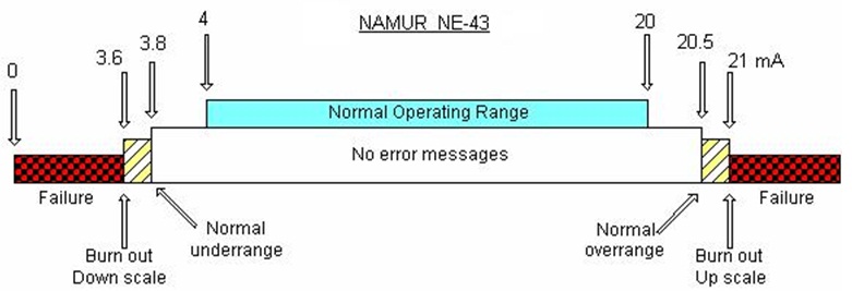
No 2-wire, loop powered field sensor will give you a less-than-zero, under-range reading at 3mA because 2-wire loop powered instruments use about 3.5mA to 3.6mA of the current loop current to power their own internal operations. So current levels below 3.5/3.6mA is not available as a proportional process variable signal.

The chart below shows the allocation of current levels for various functions: DC power, failsafe low, under-range PV, proportional PV, over-range PV and failsafe high. It reflects NAMUR standard values which are not necessarily the same a vendor's own values, but the values will be close.


NAMUR-s-4-20m-A-map.jpg


4-wire devices (generally) can power a 0-20mA signal because the signal wires are not used to power the output. The exception is a 4-wire device that allows for 2-wire output powered by a loop power supply.
 
Thanks, GaryS. Anything less than 4 ma will be shown as 0 and not negative. That's why drbitboy asked to configure as 0 to 20ma.
 
Thanks, danw for the detailed explanation. True that normally a good transmitter would never give 3mA but just wanted to know how to get negative readings on HMI in case the mA reading falls below 4 mA.
 
I just noticed this:
TIP
The Input Minimum, Input Maximum, Scaled
Minimum, and Scaled Maximum are used to
determine the slope and offset values. The input
value can go outside of the specified input limits and
no ordering is required. For example, the scaled output value is not necessarily clamped between the
scaled minimum and scaled maximum values
Huh. I have been assuming it was clamped, which would explains OP symptoms, but does not seem to be the case. Perhaps OP is not using the SCP instruction?
 
The SCP instruction does not clamp. The 1746-NI4 does if i recall correctly EDIT: No, I was wrong. I will find a program with one in it and see what we did. I am pretty sure there is a way to detect out of range conditions on any of these cards, but the SLC have some variation among the different catalog numbers so I haven't committed any of them to memory.

EDIT: The 1746-NI4 uses a range of 4mA = 3277 to 20mA = 16384 and does not have any built in scaling options. It can register as low as -20mA = -16384, but does not have any built in bits for under-range or over-range. You can set up your own limits in ladder logic to detect a sensor signal that is out of range. It has dipswitches that allow each channel to be set up for voltage mode that by default are set ON for current mode.

On another thread, someone suggested we compile a spreadsheet with all of the scaling for A/B analog modules, so I started one today.

So in the OP program, something is clamping the scaling and it could be in the HMI, but is most likely in the PLC code.
 
Last edited:

Similar Topics

Hi all Dear i need to send 4-20 MA wireless to remote location distance is 8km. What is best design for that. I think to use S7-1200,AI SB and...
Replies
24
Views
6,699
Hi all, I'm connecting several 4-20mA sensors together in parallel (only one shown below) The enclosure is ABS plastic with metal backplate DAQ...
Replies
5
Views
258
Problem: Our PLC can only output 4-20mA, but the actuators it needs to control, modulate based on a 0-135Ohm signal. Buying 4 or 8 individual...
Replies
7
Views
267
What's your go to 4-20ma isolator. I've got some 4 wire 4-20ma from several flow meters and scales that I would like to isolate before it gets to...
Replies
10
Views
1,679
Hi, I need to read three 4-20mA signals from a DCS(ABB) in a remote 6 channel analog input module with RS485 modbus port. When I connected...
Replies
2
Views
477
Back
Top Bottom