single push/ double push variation using mitsubishi FX1N

taknevs

Member
Join Date
Jan 2003
Location
Memphis, TN
Posts
25
hi all,
i am writing a ladder logic in which i need to distinguish between single push and double push of a Pushbutton (similar to single click and double click using a mouse). i am using mitsubishi FX1N PLC and GX developer ver. 7 software.
A single push of the pushbutton (input X0) should perform one operation (say activate output Y0) and double push of the push button should perform another operation (activate output Y1). The PLC will look for single or double push within a certain timeperiod say (1 second) That's why I have used a 1 second timer in my program.

This is the program:
LD X0
OUT C20 K5
CMP K0 C20 M0
LD M1
SET M15
LD M15
OUT T20 K10
LD T20
CMP K1 T20 M3
LD M4
SET Y0
LD T20
CMP K2 C20 M6
LD M7
SET Y1
END

I am sorry I could not give the picture of the ladder logic i dont know how to get it from GX developer software. If anyone have any suggestions, pls let me know.
NOTE: I tried to achive the same result using AB micrologix1200 and I could easily get the single push/double push variation.
thanks in advance
taknevs
 
taknevs,
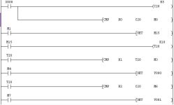
First off is this the correct translation from list code to ladder code?
Second, is this a project for school?
Last, does this code need to be repeatable? IOW, I see a lot of SET instructions, but no RESET.
Let us know,
Tim

help.jpg
 
Thanks for the translation, Tim. Looks correct... :D

For my purposes, it will be easier to use the original format.

LD X0
OUT C20 K5
CMP K0 C20 M0
LD M1
SET M15
LD M15
OUT T20 K10
LD T20
CMP K1 T20 M3
LD M4
SET Y0
LD T20
CMP K2 C20 M6
LD M7
SET Y1
END

The first thing I see wrong is what I've highlighted above. Shouldn't that be C20, not T20? Might just be a typo?

Second, you'll have a much easier time if you use inline comparisons. Yes, they DO exist on the FX1N (I didn't know this either... See my earlier "sucks" thread, specifically starting with THIS POST from Bob).

Please tell your teacher that this is was a lousy "example application" to use in learning about comparison instructions... :rolleyes:

beerchug

-Eric
 
From Tim: First off is this the correct translation from list code to ladder code?
Yes this is the correct translation for the code. This code also needs to be repeatable, but I will have another pushbutton input to reset everything, that's why I didnt mention it in the query.

From Eric Nelson: The first thing I see wrong is what I've highlighted above. Shouldn't that be C20, not T20? Might just be a typo?
Ahhhhh! Yes that does look wrong. That is not a typo and I should have entered C20 instead of T20. I will try it and let you guys know.

From Eric Nelson: Please tell your teacher that this is was a lousy "example application" to use in learning about comparison instructions...

I actually intend to write ladderlogic for automationg sequencing of events (like moving a scissor lift up or down or rotating a stage carousel to 3 diff. positions) for cues in a theatrical production. Since I have to use Mitsubishi FX1N plc which has only 8 inputs and 6 outputs, I ran out of inputs. Using 6 inputs for limit switches, I have only 2 remaining for pushbuttons with which I need to perform three operations:
Press PB1 : Go to next cue
Press PB2 : Stop
Press PB2 twice : Go to previous cue
Each cue has a specific set of actions to be done. I hope I didnt bore you with too many details.

Thanks a lot.
taknevs
 
Still not working!!!

Eric Nelson,
That T20 instead of C20 was really a typo. The logic is still not working. Anyways I have given the corrected code below:
LD X0
OUT C20 K5
CMP K0 C20 M0
LD M1
SET M15
LD M15
OUT T20 K10
LD T20
CMP K1 C20 M3
LD M4
SET Y0
LD T20
CMP K2 C20 M6
LD M7
SET Y1
END

Can you find any logical error? What is ****ing me off is the same logic works fine for AB PLCs but not for Mitsubishi FX1N (which is the one I have to use.)
Thanx again
 
It's probably something simple, but I don't have an FX laying around to see what's wrong. It might help if you post the "working" A-B version so we can figure out the difference(s). This will also help explain what you're trying to accomplish.

The A-B will not directly translate, so I'm guessing that the problem has to do with the translation. One thing I'm confused about is what the first compare instruction is doing.

LD X0
OUT C20 K5
CMP K0 C20 M0

The counter (C20) increments each time the pushbutton is pressed, that's straightforward. The confusion is with the CMP. With what you have written, when the pushbutton is pressed, the current counter value is compared to zero. I'm not sure how this will work, as the counter will only = zero BEFORE the pushbutton is pressed... :confused:

Next...

LD M1
SET M15
LD M15
OUT T20 K10

You're using the "equal to" bit (M1) from the comparison (equal to zero in this case) to start a timer (T20), set at 1.0 seconds. Based on when M1 will be ON, the timer will start immediately when switched to RUN (unless the pushbutton is being held.

Wait a minute, are you using a N.C. pushbutton as the input? IOW, is the input OFF when the pushbutton is pressed? That would a lot make more sense... :nodi:

beerchug

-Eric
 
atlast got it to work!!!

eric nelson and tim,
i atlast got it working. here is the code just in case you are curious.

LD X000
OUT C20 K5
LD X000
CMP K1 C20 M0
LD M1
SET M15
LD M15
OUT T20 K15
LD T20
CMP K1 C20 M3
LD M4
OUT Y000
LD T20
CMP K2 C20 M6
LD M7
OUT Y001
LD Y000
OR Y001
RST C20
RST T20
LD X002
RST M4
RST M7
RST M15
END

i need to know whether i have used a round-about way for the logic instead of any straight forward method. Thanx again
taknevs
 
tak,
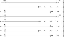
Your problem lies in your compare statements. Remember that S2 is less then S1-Bit device D is on, if S2 is equal to S1-Bit device D+1 is on, if S2 is greater then S1-Bit device D+2 is on. Look at what I have changed in the new ladder code. You were just about there and also the first compare statement is really not neccessary.

cmp.jpg
 
:eek:
Fellows, Please excuse my last reply. MAN, Its been a long day. I had know idea what I was thinking.WHEWW
Good job taknevs,
The only thing I see right off is first compare statement. You really could do without it.
Good Luck
Tim
 
I think I have two solutions. First try this:

LD X0
OUT C10 K5
LD> K0 C10
OUT T10 K10
LD T10
MPS
AND= K1 C10
SET Y0
MPP
AND> K1 C10
SET Y1
LD T10
RST C10

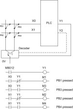
From what I understand you have not enough inputs in the PLC.
The second solution is hardware and software combination. If you have at least one output available you can double number of switches or buttons in your system. If you are interested in this please replay to this post.

-Krys
 
eric, tim and krys,
thanx for all the suggestions. i guess i can do without the first compare statement. i will implement it and let u know how it worked.

Krys: From what I understand you have not enough inputs in the PLC. The second solution is hardware and software combination. If you have at least one output available you can double number of switches or buttons in your system. If you are interested in this please replay to this post.

yes, all suggestions are welcome.

thanx again
taknevs
 
I have what might be a better alternative to your single/double push method to create the two functions... A lot easier to code as well.

Push and release = Function 1 (I'd make this the most often used function)
Push and hold for 1 sec. (or whatever amount of time you choose) = Function 2

You can just look for the transition from on to off (i.e. trailing edge) to trigger Function 1, and the timer expiring to trigger function 2. You'll need to use the pulse instructions. In my ladder, --]^[-- is a rising edge pulse (LDP), and --]V[-- is a trailing edge pulse (LDF)...

| X0
|---] [-----------------[OUT T20 K10]
|
| X0 M2
|---]V[------]/[--------[SET M1]
|
| T20 M1
|---]^[------]/[--------[SET M2]
|
| M1
|---] [-----------------[OUT Y0]
|
| M2
|---] [-----------------[OUT Y1]
|
| X2
|---] [------------+----[RST M1]
| |
| +----[RST M2]


.
Basic operation...

When the pushbutton is pressed, timer (T20) starts timing. When the timer expires, set Function 2. If the pushbutton is released before the timer expires, set Function 1. Notice the interlocks on the SET rungs. These allow only ONE function to set to avoid problems (e.g. Operator presses PB again). As you described in your most recent post, I used your X2 input to reset the functions.

Note: I did not test this code, so it may need debugging. I'm sure if I did anything blatantly stupid, other will chime in... lolis

beerchug

-Eric
 
Thanks for the verification, Tim... ;)

This "hold for second function" comes in pretty handy. Especially when you're dealing with a limited number of membrane keys on a text display. I hate 'wasting' keys for rarely used functions. For example, let's say you're filling a box with a preset number of parts. You press a key momentarily, and the display shows the current quantity of parts in the box as it's filling, but if you HOLD the key for 'x' seconds, it allows you to adjust the preset.

Operators seem to pick this up pretty quick, as it's similar to how a car radio's station buttons work. Press and release to switch to that station, but HOLD for a few seconds, and it places the current station in that button's memory. Many people don't realize that the station doesn't change when you PRESS the button, it changes when the button is RELEASED!... :nodi:

beerchug

-Eric
 
taknevs

I was looking for any information in this site on how to post an image but couldn't find. I still do not know how to do this so I attached the picture to this post.
The picture shows only an idea on how to increase the number of inputs when there are some outputs available. This technique is use for connecting keypads. It is recommended that it is used only for buttons and switches.

- Krys

fx - example.jpg
 

Similar Topics

Hi, So I have one push button(non-latch momentary) and would like use it to trigger two function sequences with the short press for primary...
Replies
3
Views
1,988
I'm a beginner in PLC education, struck with a problem. Anyone can please help. The problem is: I have a single push button. When I press &...
Replies
30
Views
15,197
Why does the controllogix redundancy modules use a single mode fiber vs multimode fiber?
Replies
1
Views
78
I am converting a SLC 500 to a Compact Logix. I plan on using a Compact Logix 5380 with conversion Kit. The problem is that the analog input cards...
Replies
1
Views
146
Hello, friends, I am trying to upgrade a system that uses an Onrom incremental encoder (E6B2-CWZ6C) connected to a Danfoss VFD (FC360), but now...
Replies
4
Views
271
Back
Top Bottom