PLC Parking Garage Program

CraigY49ers

Member
Join Date
Jun 2015
Location
California
Posts
38
Hello Everyone,

I am working on a program to run on a Direct Logic D0-05 DR-D PLC for a parking garage program. I have a program I wrote that does most of the functions I need already but I need a little help. I need to find an easy way to flash a yellow light at a 1 second interval until the count changes to 25 cars or under 23 cars? I am using three NO push buttons and one NC pushbutton for inputs. The only outputs are a red, yellow and green stack light that signifies the status of the parking garage. There may be other things I have missed and any constructive criticism will be appreciated. I will attach my program to this post so you can see what I already have. I am programming in RS Logix the I will have to translate it to the DirectSoft 100 software after I get all the bugs out of it. I will attach a copy of the requirements so you will have an idea of what I am working towards. I also have version I am working on trying to translate the RS Logix program I have to DirectSoft 100 and could use any help on that as well. I will attach it to this discussion also.

Sincerely,

Craig Y.
 
I need to find an easy way to flash a yellow light at a 1 second interval until the count changes to 25 cars or under 23 cars?
In RSLogix 500, use one of the internal clock bits at Status word S:4. Bit S:4/9 should produce a 1 second on time and then a 1-second off time. Increasing the bit number increases the flash time, decreasing the bit number decreases the time.

Here are 6 flasher methods for the RSLogix 500 softweare.

6 FLASHER METHODS.jpg
 
Last edited:
Here are a few comments based on a first look at your DirectSoft 5 program:

1. On rung 1, you have assumed that the Start and Stop pushbuttons are maintained-contact pushbuttons. Usually in the real world, Start and Stop PBs should be momentary-contact buttons. If your actual buttons are correct and are really momentary-contact spring-return buttons, then you need a seal-in contact in parallel with your Start PB.

2. For Rung 1 also, your instructions say:
At the end, a NC pushbutton is pressed to stop the process and reset all counters.
If you used the physical NC pushbutton, then your instruction FOR THAT BUTTON in the PLC must be a NO contact, so that it is ON when the STOP pushbutton is NOT PRESSED. This is a small point but an error which will reduce your grade.

3. Rung 2: You have an "Almost Full" Up-Down counter set at 23, and a "Full Counter" set at 25. You can greatly improve your program if you delete the Almost Full Counter and only use the Full Counter that counts up to 25, the full level. For the Almost Full condition, simply use two comparison instructions that look at the Counter Value. (Use the Greater-Than-or-Equal-To AND Less-Than contacts). The Counter 2 Value = CTA2, and "23" count = a K23 constant, and "25" count = K25.

As Doug-P said, use the Special Relay contact SP4 to generate the 1-second On/Off flashing effect. For example, if you keep CT2 as your Full Counter, then on your rung 3, change it to look like this:

If CTA2 >= K23 AND CTA2 < K25 AND NO contact SP4, then Y1 OUT "Yellow Light ON"

I don't think you have handled the OFF condition for the Green Space Available Light, as required by this statement:
If the number of parked vehicles in the garage is 23 or 24, the green light is turned off and a yellow light flashes continuously at the rate of one second on and one second off.

Again, use a comparison contact (CTA2 > K22) that you insert in your Rung 1 (after you figure out what kind of physical Pushbuttons you have and fix that problem first).
 
Last edited:
For your Rung 1, if you put the Green Light here as a "Run" relay, then when it turns off at Counter > 22, your RUN relay will also be off (even though the system has to stay in RUN mode until STOP is pressed). I suggest you use C0 as a RUN Mode Relay on Rung 1, then use a N.O. contact for C0 AND a comparison contact Counter < K23 on a new Rung 2 to control the Green Light Y0.

Note that when the lot is closed (RUN Relay is off after STOP is pressed), the counter should not count if the janitor accidently trips the X3 "Car Entering Lot" pushbutton, or the X4 Car Leaving pushbutton either). In other words, lock out the counter by using a NC RUN Relay, another reason that you need that relay.

I noticed that you did NOT use the Input addresses as instructed, mixing them up differently. I would count off some more points here for not following the customer's directions. Your instructions give Inputs for X1 to X4 (no X0 used). Yes, I know your Inputs will work just as well, but instructors set these things up so they are easy to check. When you mix up the addresses, that causes them extra work, extra aggravation, and do you want him/her aggravated when they assign your grade?

If you work on it and set it up correctly with a C0 RUN Relay, you can use 6 rungs including END, with one Counter, and 3 comparison instructions (one for the Green Light, and 2 for the Yellow Light).
 
Last edited:
Hello Lancie1,

I appreciate all of the input on the potential problems in my program. I am trying to implement some of the suggestions you made now. I have changed my NC pushbutton contact to NO contact as you suggested. I am working on trying your suggestion on using just one up and down counter. The buttons I am using are NO Pushbuttons except for the Red one and it is a NC Pushbutton. I am also going to use a comparison contact that you mentioned on rung one. If you see any other potential problems I greatly appreciate your input.

Sincerely,

Craig Y.
 
Hello Everyone,

I am working on implementing the changes you suggested in earlier post. I would like to ask a few questions though about the comparison instructions. If I delete the almost full UDC counter and use the full counter do I place the comparison instructions after the full UDC counter? I was also wondering if I replace my green switch contact with the compare instructions that were suggested or would they come after it? We did not learn anything about the compare instructions in my PLC course so that is why I am asking to make sure about them. I again thank you for your input and would appreciate any further input you have to give me.

Simcerely,

Craig Y.
 
Hello Everyone,

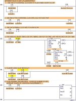
I have reprogrammed my original program with the changes that everyone suggested. I have not tried it yet on the PLC but that will be my next step. I have changed the two timers to one and used compare contacts for the other counter instructions. The yellow light has been moved and a compare instruction has been added to control that as well. At first this programming of the PLC looked very complicated and it can be especially if you have never done it before. Using RS Logix's simulator is a whole different ball of wax than actually hooking up a PLC and programming it with a whole different program. I really appreciate the help you guys have given me on this project. I was just wondering how I should program the output coil on rung 1? Should it be addressed for the green light? Or a timer bit? I am going to attach a copy of my streamlined new program so you can look at what I have now and make constructive comments on it.

Sincerely,
Craig Y.
 
1. You used Y0 twice, in Rung 1 and Rung 2. The last rung will control the final output.
2. Place all your light rungs together, after the UDC rung place the Green Light rung, then the Yellow Light rung, and then the Red Light rung. This will help you to think about how the lights are operated since their logic is grouped together. This should help you find the error in your Green Light logic.
3. Your Stop Button (Red Switch) is actually a reset button for the UDC.
4. In rung 1 C0 is called a green button, did you mean to use X0?
 
Parking Garage Program

Hello everyone,

I was trying to use C0 as a RUN mode relay for the Green Light. But I am not sure what kind of coil to use at the end of rung 1? If you can look at the description of my project it may help clear up what I am trying to do. I am not to sure about using C0 but it was suggested by one of the programmers earlier. I just need to have the green button start the program and get it running. I placed all of the rungs for the lights together to make it simpler. And I used Y5 to end the first rung so hopefully it will lock the program in the run mode. I will post a copy of my project and a copy of my current program so anyone who wants can look and make constructive comments. I am wide open to any comments on my programming because I really want to learn how to write these programs.


Sincerely,

Craig Y.
 
Parking Garage Program

Hello everyone,

I was trying to attach a graphic of my program to the last post but it just would not attach. So I will attach it here and anyone who wants can look at it. Thanks everyone for all of the input on my project and program. The file was too big so I had to shrink it down but here it is now.

Sincerely,

Craig y.
 
You have made progress. I will try to answer your questions first.
If I delete the almost full UDC counter and use the full counter do I place the comparison instructions after the full UDC counter?
In this case (usually the normal situation), it will not matter if you place your comparison before or after the UDC counter. Remember the PLC scans from top to bottom, then repeats. So if you put comparisons for the Counter before the Counter instruction, then your comparisons will run on the next scan after the counter makes a change - 1 scan late is no big deal here, cars will not enter or leave during 1 PLC scan.
I was trying to use C0 as a RUN mode relay for the Green Light. But I am not sure what kind of coil to use at the end of rung 1?
If you want to use the internal relay bit C0 as your RUN Mode Relay, then use an Output coil at the end of the rung, with address "C0". Yes you could use Y5, but that is a physical Output and those are precious and costly. Unless you also have a light for the RUN Mode (no RUN light output is listed in your instructions), then there is no need to waste a physical PLC Output. Instead use an internal "no-cost" PLC bit such as "C0".

I just need to have the green button start the program and get it running.
NO! There is more! Read your instuctions again! You also have to STOP it by pressing the red STOP pushbutton.
At the end, a NC pushbutton is pressed to stop the process and reset all counters.
That means you can't use the Green Light as a RUN relay. The system has to keep running even when there are from 1 to 3 spaces left (while green light is OFF). If someone leaves, then the green light must go ON again, that same day BEFORE your press STOP to shut down the system. That is why you need a separate RUN relay. This is common in industrial plants so learn how to do a RUN relay. It is the proper way to do this program. The STOP button has to performs 2 tasks, unseal the RUN relay (note a seal-in C0 contact should be in a parallel rung branch with your START Pushbutton) and also reset the counter as per your instructions.

You should add rung comments on each rung that explain what it does or how it works. See the attached example.
 
Last edited:
You should change the label for Counter CT0 from "Lot Full" (that is only true when CTA0 = 25) to "VEHICLE COUNTER", its true purpose.

Also, double check your comparison constants to make sure you have met the instructor specifications (hint: When there are 3 spaces left, Counter value CTA0 = 22, 2 spaces left and CTA0 = 23, 1 space left and CTA0 = 24).
 
Last edited:
Hello Everyone,

I have been busy working on my Program and wiring up the lights on my project. I think that I have now got it to the point where I can download it to my PLC and try it out. I just wanted to post a copy of my latest program for your perusal. With your help and guidance I have gotten my program to this state. I really appreciate all of the guidance you have given me and I look forward to keep on learning about what and how you can program a PLC to do. Without your guidance I would not have gotten to this point. So I applaude you and thank you for your help. I have included a couple of pictures of my project below. It is not perfect but for my very first PLC project it is not totally bad. I wish I had a bigger budget so I could get exactly what I needed but I had to make do with some parts.

Sincerely,

Craig Y.
 

Similar Topics

This is the reason why I signed up here and decided to get some help before I tackle the traffic light program on Wednesday. It looked good on...
Replies
17
Views
11,702
Hi guys.. Pls i need some help. I.m about to make a plc parking sistem (for school) with an elevator .. i must collect all the inputs/outputs ( i...
Replies
8
Views
2,867
Hey guys ! I am new to this forum. So, I hope you guys don't mind my noobiness :p . I am working on my Final Year Project which aims to design...
Replies
196
Views
123,756
Hello, I am trying to create a program for Omron CJ1M PLC for a Parking Lot Control System. The system design is as follows: 1. Sensor detects a...
Replies
5
Views
4,539
Hello all. Finally my final year project was successful done. Here i attached the video to share with all of you. I would like to give special...
Replies
2
Views
5,501
Back
Top Bottom