Wiring a float switch to a PLC. What next?.….

Mas01

Member
Join Date
Oct 2020
Location
Leicester, England
Posts
1,107
Hi, On a previous thread I asked about how to connect a float switch to a PLC.
http://www.plctalk.net/qanda/showthread.php?t=126829

As I'm a complete novice and feeling completely out my depth, once I've connected the switch, in general terms, what are the next things I need to do?
Ultimately, I want to monitor the water level in a tank by monitoring the switch (closed when water is at the level of a switch) on a screen (done in GX designer?). And also I imagine I need to update the PLC software to recognise the new data (switch position).
Please can someone help me with a general list of things I need to do once the switch is connected to the PLC, and which software to use at each stage. I know we have GX developer and GX designer and something called GOT but not sure what that is for.

Thanks
 
Last edited:
First I would want more than one switch...

Float at the top to Stop the fill pump
Float at the bottom to Start the fill pump

And some people have another at the top and bottom for safety, if necessary these would be to set an alarm and/or to stop a process

After wired start the pump when the lower switch is showing empty and continue to fill until the top switch is made then stop the pump (break the latch)

Thanks for the reply, but what I meant was what steps do I need to do in the PLC development phase. E.g. get the PLC to recognise the new switches (to recognise the new input parameters), create a new screen using GX developer to show a live schematic of the tank with water level position, etc etc
 
Last edited:
I think you mean GT Designer that is for programming HMI's GXdeveloper is for the PLC's in ladder or STL, GXWorks2 or 3 is the later versions for programming the PLC's using FBD, Ladder, ST etc. If your file is pure ladder then GXDeveloper is fine, You can load a GXDeveloper file into GXWorks but what it does is use it in GXDeveloper mode so I suggest you keep it as GXDeveloper.
First of all, you need to know the address of the input you are using, this will depend on the rack position & the types of cards in the racks. for example if the card you are connecting to is a 16 way input card in slot 0 (closest to the Processor) then the inputs would be X0-X7 and X10-X17 (They use what is called octal addressing). If you know what other inputs on that card do then find one in the program i.e. it could be x7 then this is the eighth input but address 7, and then the following inputs will be X10 to X17 (8-9 are not in use).
Then you need to decide what you want the switch to do i.e. run a pump, stop a pump if it is on or off. It sounds like you have little or no experience in PLC programming and I suggest you do not attempt this on a live system, you could cause all sorts of problems. You need to practice going on-line, comparing programs with back up files, understanding how the system works, how to write code & download it. For just displaying it on the HMI then you will not need any code in the PLC, Just connect the switch to the input & identify which input address it is for example X6 then load the HMI file into GT Designer (assuming the HMI you have has been programmed using this), Then compare the file with the GOT screen to check it is correct (Communication/Verify) If ok then select the page you wish to display the level switch on and drop a BIT Lamp (Bulb Symbol) from the selections on the right hand tabs onto the display, re-size it if required and place it in some sort of position. Then double click it this opens a dialog so you can enter the PLC address i.e. X6 in the Device field, change the colour depending on what you want for the bit status i.e. on/off default is black off Red on. save the project then download it to the HMI. When the HMI is running it will display the colours you selected depending if the input is on or off. Warning, if you make a mistake it may take you some time to get it back to the way you want it. As I said this is not for beginners especially on a working system.
Your only in Leicester so I'm 30 miles away if you want send me a personal message with your email perhaps I could help by looking at the code
I can actually load the plc code & The got into simulators & test it.
@parky, That's an absolutely fantastic reply, I'm really grateful. I need to be careful about sharing files- customer confidentiality and all that, but maybe I can 'desensitise' it to make it more general.
Of note, the work I'm doing is like a 'bolt-on' to an existing system which already works....my job is to update the PLC to monitor the water level in the tank. The tank has been there years and we've never had issues with the level before, so I wouldn't call it a critical system as such, it's just that now someone decided it'd be good to monitor it from the comfort of the control room, rather than a person stood next to it during running.
Thanks again @parky.
 
Last edited:
That's fine I'm retired now so I do occasionally help people out. As I said, if all you need currently is an indication on the screen then you do not need to touch the PLC code at all, the I/O is already configured so can be seen by the HMI.
The lamp widget was just an idea if it was me I would have put low & high levels in but that's me. You could use any form for the status of the level switch
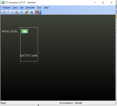
This took me about 30 seconds to put a simple tank on with a square indicator for the high level. There is no code in the PLC for the input I just force it on or off in the simulator for the PLC

Tank Level.png
 
That graphic looks impressive to me!
Music to my ears if I don't need to touch the PLC code.
For info, there are 4 strategically positioned float switches, but thus far I have only talked about 1 switch for simplicity. when the facility is not running a test, Ideally I'd like to do a 'stand-alone' test and manually close the float switches (tank is empty at the moment) and see the HMI/screen buttons change colour accordingly.
That would be a huge achievement.
 
Last edited:
As a matter of fact what Model of GOT is in the system and what GT Designer version have you because I could do a simple example so you can open up the page and look at how I did it.
 
Yep your right, you can take the programmer out of programming but you can't take programming out of a programmer I think I heard some similar saying somewhere 👨🏻‍🏫
 
Ideally you would want a high level, a low level and a working level (assuming something fills your tank and a pump pumps it out)

You latch fill at working level and unlatch at high level, the low level protects the pump pumping out.

The high level switch is at the top of the tank, the low level before the pump outlet and the working level around half way.

The principal being you start to fill the tank @ the working level until it gets to the high level. If you fill the tank at the low level, you have to wait for it to fill and the pump will be stopped whilst at the low level whilst the level goes above it.

If it is not full and not working level, then latch fill until working level and high level.

If it is low level then stop the pump.

If you have low level and high level, stop the pump and alarm as something is wrong.
If you have not working level and high level, stop filling and alarm.

And so and so forth.
 
@janner_10...Thanks for this, it's really useful. I'll check next week, but I think our switches are located in the positions you describe, plus an extra one between the working level and the low level. This water is used as part of a cooling system, so we plan to monitor (or currently do monitor, not sure which) the water temperature too.
 
Here is a quick & dirty tank with digital levels in GT Designer 3.
I have just put some standard symbols on it to show you how you can represent the levels (of course there are many ways i.e. create your own).
I have used "M" bits so you will use the X inputs as the PLC tags.
I have shown a couple of ways so indicators with text and a sort of bar graph made out of rectangles and the states change depending on the status of the bits. You can change the colours as you wish I have used amber for low low, green for mid & high & red for high high the high high level also flashes to draw the operator to an overfill, just me being pedantic lol. This may not be the GOT version you have but if you have GTWorks3 then you could open it and double click on the symbols there it will show you how to add the PLC addresses and select the colours etc.
 

Similar Topics

Hello, I have a float switch that is labeled as below and has only 2 wires (red,black): Input 10-30VDC Output 4-20mA Resolution 5mm I am...
Replies
11
Views
3,334
Posted this to Reddit with little success, so I figured I would share it here as well. Very new to PLCs, but figured I would give it a shot to...
Replies
0
Views
122
Hello Folks, Has anyone configured a Momentum high speed counter on Unity 13.1. We need the wiring diagram for Momentum High speed counter and...
Replies
0
Views
76
Hey guys, the scenario is: I have already completed the drawing package for my system utilizing an A-B 440R-N23126 (Minotaur) safety relay. SoS...
Replies
0
Views
136
Maybe a stretch to call this a PLC question, but it does connect to a PLC input. I have two German switches: Sick WL9LG-3P2232 And a...
Replies
0
Views
109
Back
Top Bottom