Mitsubishi GT Designer3 - question about timerers (T)

Mas01

Member
Join Date
Oct 2020
Location
Leicester, England
Posts
1,105
General question:
I've got a 10-second timer T100 in my code.
As the counter increments, does it automatically get reset to zero once it reaches its target value (K100) - as opposed to remaining at 100? Assuming that rung is still active, of course.
Hope that makes sense.
 
Last edited:
No it does not reset, if the rung is true it will stop at the value for the timer, once the contact that starts it goes false the timer contact goes off & the timer accumulator resets back to 0.
 
Thanks, the reason I was asking is that I want a 10 second delay before turning off a sump pump to account for any "debounce" in the lowest float switch, ie the float switch might jump around a few times due to turbulence of circulating water. Then I want to reset the timer.
At the moment I don't think the timer is going to reset.
 
Last edited:
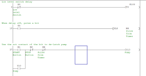
What you can do is generate a pulse (one shot) from the timer
So when the delay timer is up use the one shot bit to disable the pump latch
Or if you use a pump set/reset bit just use a N/O of the pulse to reset the bit
As the one shot is only on for one scan it will turn off the latch but allow a re-start of the pump.

Pulse.png
 
What you can do is generate a pulse (one shot) from the timer
So when the delay timer is up use the one shot bit to disable the pump latch
Or if you use a pump set/reset bit just use a N/O of the pulse to reset the bit
As the one shot is only on for one scan it will turn off the latch but allow a re-start of the pump.

Brilliant, I like the idea of the pulse. Neat solution.
 
You've already got Parky's solution, which has the added benefit of being easy to understand. There is also the TOF instruction, which sometimes seems the devil's spawn, but it was designed for this.

I.e. see the Debounce Pattern (http://www.contactandcoil.com/patterns-of-ladder-logic-programming/debounce/) from ladder design patterns (http://www.contactandcoil.com/patterns-of-ladder-logic-programming/).


Matter of taste.

Thanks bitboy. Looks interesting but as I'm a novice, I'd probably be out of my depth... pardon the pun.
 
Putting a N/C contact is the same thing, however, GXDeveloper does not have IEC Functions or TOF timers. You would need to use GXWorks or GXIEC for TOF timers.
 
Putting a N/C contact is the same thing, however, GXDeveloper does not have IEC Functions or TOF timers. You would need to use GXWorks or GXIEC for TOF timers.


whoops, I saw TOF as an invalid label in a GX Dev. manual and assumed.


My bad, thanks!
 
What you can do is generate a pulse (one shot) from the timer
So when the delay timer is up use the one shot bit to disable the pump latch
Or if you use a pump set/reset bit just use a N/O of the pulse to reset the bit
As the one shot is only on for one scan it will turn off the latch but allow a re-start of the pump.
Brilliant - implemented this and pump switches off as expected.
 
I loved the simplicity of Mitsubishi ladder, just one type of timer for any kind of timing.
 
Brilliant - implemented this and pump switches off as expected.


Just thinking: perhaps an NO of the pump output bit should also be in series with the NO of the low level switch on the rung feeding the timer (rung 0).


An alternate approach would be to put either a NC of the timer done (T0) bit, or a NC of the low level, in series with the start button NO contact on the upper branch at the left side of the start/stop circuit (rung 37).

The reason is that, the way it is now, if the low switch generates a one-shot that turns off the pump, and if someone then turns on the pump, then the pump will come on and stay on, even though the low level switch is on, because the timer done bit is not reset and the one-shot has already fired.


A third option would be to put a NC of the T0 done bit on the rung feeding the timer (rung 0). That would make the timer reset itself (assuming Mitsi timers work that way; I'm ingnarant here, obviously), the second rung (18) and the intermediate bit (M4 pulse from timer) could be eliminated, and the T0 bit could be used on the last rung instead of the pulse bit.


Either of the first two should work; the third is just a code golf things that may not work in Mitsi-land.


I am not saying there is anything wrong with @parky's start/stop circuit in principle; it may even be the case that the "feature" of allowing the pump to run while a low level is in effect is intentional; rather there is an edge case here that should be considered.
 
Last edited:
It is common practice to run the pump for a time on low level detection as the pump will create a suction, when the pump stops there is a likely hood the level in the tank will rise and cover the sensor again, this can lead to possible hunting (can be programmed out) and give false indication i.e. the display may show that the level is above minimum leading the operator to wonder why the pump stopped, yes I know alarms etc. can be generated, but I have been in this game a long time, operators & engineers seem to have this blinkered vision where they do not look at the alarm page, keep it simple. Most low levels will be above absolute empty and even if not the pump components will be wet enough to allow a short run without a head of product without damaging it.
 
...operators & engineers seem to have this blinkered vision where they do not look at the alarm page...
Yes we do, and that's the crux of my concern: if the operator restarts the pump after a debounced low level unseals that last branch and stops the pump, even if the level has risen to cancel the low level after the first stop it will not after the third or fourth (or fifteenth;)), and after that point the proposed code may run the pump automatically until well after its components are no longer wet.

So how about this:
Code:
       LowLevel                 LowLevelDebounce
---+-----] [-----------------+-----(T0 K100)---
   |                         |
   |   T0     LowLevelReset  |
   +---] [---------]/[-------+
 

      Start            Stop     Y10
---+---] [---------+---]/[------( )---
   |               |
   |   Y10    T0   |
   +---] [----]/[--+
  • Requires the operator to reset a debounced LowLevel condition (i.e. alarm as @parky suggested) before allowing the pump to run on auto (sealed-in) again even if the level has recovered. At that point we have done our best to ensure the operator is aware they are dealing with a low-level event.
  • Also, the auto-stop on low level is no longer done via one-shot, so it prevents the pump (Y10) from running automatically after the rising edge of a still-active debounced low level (T0),
  • Allows the operator to run the pump manually with a low level by holding in the Start button if needed, e.g. to drain the tank for maintenance.
  • Same number of instructions, in bog standard Start/Stop and Start Coil/Fault Coil patterns.
 
I do agree, normally I would just put the low level timer contact in the pump logic so it cannot be started until at least above low level (normally I would have a latch driven off two timers on & off so that the pump will not run until the level has been on enough to cover the probe), again to stop the pump running & stopping after a second or two. in other words a de-bounce on true & false, however, the OP wants for some reason to reset the timer (low level), I have no idea why, as far as I'm concerned you should not start the pump if below low level, but that appears to be what he want's rightly or wrongly.
It does appear from what bits of logic I have seen in his program it has not been thought out very well, there is quite a bit of I/O to make this complete process run without operator intervention, however, there seems to be lots of operator operations for example, they start/enable pumps etc. via operator interventions on the HMI, why not just one start then let the logic control the process, generate operator prompts for intervention so for example operator presses start, the tank fills to level, then allows cooling water to circulate, wait until at running temperature then allow process testing to begin. but from what I have seen this is not the case, however, there could be reasons.
 

Similar Topics

Hello! I keep getting an error when trying to open a HMI in GT Designer 3. I go to Project->Open then select my project (GOT Type GS21**-W) and...
Replies
4
Views
2,810
Hi, Complete novice on PLCs and need your help (again). On GT Designer3 what sort of button/switch do I need to add to Start/Stop a water pump...
Replies
7
Views
1,951
GTDes3, On all the tabs where the HMI screens are defined, each tab contains the words "(Front+Back)". Anyone know what this means? Thanks
Replies
1
Views
1,159
I'm absolutely stuck at this point with the recipe portion of my program. I used the default example they had on their website to create the...
Replies
0
Views
1,751
Hi Friends, who could please tell me how to add users Security in Mitsubishi GT Designer3? I will be grateful Regards
Replies
0
Views
1,720
Back
Top Bottom